
User`s manual


9 - 99 9 - 99
MELSEC-Q
9 CONTROL OPERATION INSTRUCTIONS
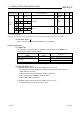
Control data
(1) Data specified in S.PGS instruction
Specified position Symbol Name Recommended range
*1
Unit Data format
Standard
value
Store
D1
+0
+1
BW Output value (-999999 to 999999) %
Real
number
S
BB
BB1 Alarm
BB2
Output upper
limit alarm
Block
memory
+2
BB3
Output lower
limit alarm
b15 b12 b8 b4 b0
B
B
3
B
B
2
B
B
1
(0: Without alarm)
(1: With alarm)
BIN
16bit
S
D2
+1 MODE Operation mode
0 to FFFF
H
b15 b12 b8
b4 b0
L
C
C
L
C
A
L
C
M
M
A
N
A
U
T
C
A
S
C
M
B
C
A
B
C
C
B
C
M
V
C
S
V
BIN
16bit
8
H
S/U
+3 ALM Alarm detection
0 to FFFF
H
b15 b12 b8 b4 b0
S
P
A
M
H
A
SPA
0: Loop RUN
1: Loop STOP
MHA, MLA
(0: Without alarm)
(1: With alarm)
M
L
A
BIN
16bit
4000
H
S/U
+4 INH
Alarm detection
inhibition
0 to FFFF
H
b15
b12 b8
b4 b0
E
R
R
I
M
L
I
0: Alarm enable
1: Alarm inhibit
M
H
I
BIN
16bit
4000
H
S/U
+10 PTNO
Number of
operation
constant
polygon points
0 to 16
BIN
16bit
0U
+12
+13
MV
Manipulated
value
(-10 to 110) %
Real
number
0.0 S
+14
+15
SV Set value 0 to 999999 s
Real
number
0.0 U
+16 TYPE Operation type
0: Hold type operation
(When operation mode is AUT or CAB)
1: Return type operation
(When operation mode is AUT or CAB)
BIN
16bit
0U
Loop tag
memory
*2
+18
+19
MH
Output upper
limit value
-10 to 110 %
Real
number
100.0 U
*1: The data of the item(s) where the values within the recommended range are given in the parentheses are stored by the system.
Users cannot set the data.
*2: The loop tag memory and loop tag past value memory occupy a total of 128 words. (Refer to Section 3.3.1 for details.)