
User`s manual


9 - 98 9 - 98
MELSEC-Q
9 CONTROL OPERATION INSTRUCTIONS
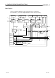
Block diagram
The processing block diagram of the S.PGS instruction is shown below.
(The numerals (2) to (5) in the diagram indicate the order of the processing.)
BW
MAN
Last BW
MHA
SPA
PTNO.
ML, MH
OR
MODE
MLA
MV
PGS
MV, MV1 to
MV16
BB1
(3) (4)
(2)
All OFF
BB2
BB3
All OFF
TYPE
(5)
SV, SV1 to
SV16
SV count-up
MV
Operation
PGS
Output
processing
Loop stop
judgment
Loop stop
processing
RUN(SPA 0)
STOP(SPA 1)
(2)