
User`s manual


9 - 90 9 - 90
MELSEC-Q
9 CONTROL OPERATION INSTRUCTIONS
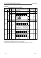
Block diagram
The processing block diagram of the S.ONF3 instruction is shown below.
(The numerals (1) to (7) in the diagram indicate the order of the processing.)
E2
BW
MAN
MODE
SPA
CT
E1
MV
HS1
RL, RH
BB1
DV
MAN, CMB, CMV, LCM
Other than MAN, CMB, CMV, LCM
(1)
(2)
(3)
(4)
(6)
(6)
(7)
BB2
(5)
HSO
RUN(SPA 0)
STOP(SPA 1)
Loop
stop
judgment
Loop stop
processing
Last BW
SV setting
processing
Tracking
processing
Control cycle
judgment
When in control
cycle
When not in control
cycle
MV output
(When
used)
Mode
judgment
3-position
ON/OFF
control
MV
compensation