
User`s manual


9 - 42 9 - 42
MELSEC-Q
9 CONTROL OPERATION INSTRUCTIONS
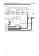
Block diagram
The processing block diagram of the S.BPI instruction is shown below.
(The numerals (1) to (7) in the diagram indicate the order of the processing.)
E2
BW
MAN
MODE
SPA
CT
E1
P, I, CT DVL, DVLS
AND
DVLA
BW=0
RL, RH
BB1
(1)
(2)
(3)
(4)
(5)
(6)
(7)
(6)
DV GW, GG
OFF
RUN(SPA=0)
STOP(SPA=1)
ERRI DVLI
Loop
stop
judgment
Loop stop
processing
Last BW
SV setting
processing
Tracking
processing
Gain K
operation
processing
Deviation
check
Control cycle
judgment
When in control
cycle
When not in control cycle
BPI operation
(When
used)
p