
Installation manual

12
GB
9. Refrigerant piping installation
The pipe is connected via a terminal-branch type connection in which refrigerant
piping from the outdoor unit is branched at the terminal and is connected to each
of the indoor units.
Themethodofpipeconnectionisasfollows:areconnectionfortheindoor
units, low-pressure pipes and high-pressure pipes for outdoor units, brazed
connection. Note that the branched sections are brazed.
Warning:
Do not use refrigerant other than the type indicated in the manuals
provided with the unit and on the nameplate.
- Doingsomaycausetheunitorpipestoburst,orresultinexplosionorre
during use, during repair, or at the time of disposal of the unit.
- It may also be in violation of applicable laws.
-
MITSUBISHI ELECTRIC CORPORATION cannot be held responsible for
malfunctions or accidents resulting from the use of the wrong type of refrigerant.
Always use extreme care to prevent the refrigerant gas from leaking while
using re or ame. If the refrigerant gas comes in to contact with a ame
from
any source, such as a gas stove, it breaks down and generates
a poisonous gas which can cause gas poisoning. Never weld in an
unventilated room. Always conduct an inspection for gas leakage after
installation of the refrigerant piping has been completed.
Caution:
Do not vent R410A into the atmosphere.
R410A is a Fluorinated Greenhouse gas, covered by the Kyoto Protocol
with a Global Warming Potential (GWP) = 1975.
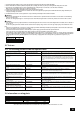
9.1. Caution
This unit uses refrigerant R410A. Follow the local regulations on materials and
pipe thickness when selecting pipes. (Refer to the table below.)
1 Use the following materials for refrigeration piping.
Material:
Use copper alloy seamless pipes made of phosphorus
deoxidized copper. Ensure the inner and outer surfaces of the pipes are
clean and free from hazardous sulfur, oxide, dusts, shaving particles,
oils, and moisture (contamination).
Size: Refer to item 9.2. for detailed information on refrigerant piping system.
2 Commercially available piping often contains dust and other materials.
Always blow it clean with a dry inert gas.
3 Use care to prevent dust, water or other contaminants from entering the
piping
during installation.
4 Reduce the number of bending portions as much as possible, and make
bending
radii as big as possible.
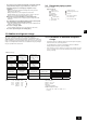
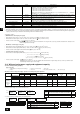
5 For indoor and outdoor branching and merging section, be sure to use the
following
twinning pipe sets and merge pipe sets (sold separately).
Indoor junction pipe kit model
Total indoor model
P100 ~ P250
CMY-R160-J1
•
•
•
•
6 Useattingifaspeciedrefrigerantpipehasadifferentdiameterfromthat
of
a branching pipe.
7 Always observe the restrictions on the refrigerant piping (such as rated
length,
height difference, and piping diameter) to prevent equipment failure
or a decline in heating/cooling performance.
8 Either
a lack or an excess of refrigerant causes the unit to make an
emergency stop. Charge the system with an appropriate amount of
refrigerant. When
servicing, always check the notes concerning pipe
length and amount of additional refrigerant at both locations, the refrigerant
volume calculation table on the back of the service panel and the additional
refrigerant section on the labels for the combined number of indoor units
(Refer to item 9.2. for detailed information on refrigerant piping system).
9 Be
sure to charge the system using liquid refrigerant.
0 Never
use refrigerant to perform an air purge. Always evacuate using a
vacuum pump.
a Alwaysinsulatethepipingproperly.Insufcientinsulationwillresultina
decline
in heating/cooling performance, water drops from condensation and
other such problems (Refer to item 10.4 for thermal insulation of refrigerant
piping).
b When connecting the refrigerant piping, make sure the valve of the outdoor
unit
is completely closed (the factory setting) and do not operate it until
the refrigerant piping for the outdoor, indoor units and BC controller has
been connected, a refrigerant leakage test has been performed and the
evacuation process has been completed.
c Braze
only with non-oxide brazing material for piping. Failure to do so
may damage the compressor. Be sure to perform the non-oxidation
brazing with a nitrogen purge.
Do not use any commercially available anti-oxidizing agent since it may
cause pipe corrosion and degrading of the refrigerant oil.
Please contact Mitsubishi Electric for more details.
(Refer
to item 10.2. for details of the piping connection and valve operation)
d Never
perform outdoor unit piping connection work when it is raining.
Warning:
When installing and moving the unit, do not charge the system with any
other refrigerant other than the refrigerant specied on the unit.
- Mixing
of a different refrigerant, air, etc. may cause the refrigerant cycle to
malfunction and may result in severe damage.
Caution:
Use a vacuum pump with a reverse ow check valve.
- Ifthevacuumpumpdoesnothaveareverseowcheckvalve,thevacuum
pumpoilmayowbackintotherefrigerantcycleandcausedeteriorationof
the refrigerant oil.
•
8.1. Installation
[Fig. 8.1.1] (P.3)
<A> Without detachable leg <B> With detachable leg
A
M10
anchor bolt procured at the site.
B
Corner is not seated.
C
Fixing
bracket for the hole-in anchor
bolt(3locationstoxwithscrews).
D
Detachable leg
Fix unit tightly with bolts so that unit will not fall down due to earthquakes or
strong winds.
Use concrete or an angle bracket for the foundation of unit.
Vibration may be transmitted to the installation section and noise and
vibrationmaybegeneratedfromtheoorandwalls,dependingonthe
installationconditions.Therefore,provideamplevibrationproong(cushion
pads, cushion frame, etc.).
Besurethatthecornersarermlyseated.Ifthecornersarenotrmly
seated, the installation feet may be bent.
When using cushion pads, be sure that the full width of the unit is covered.
The projecting length of the anchor bolt should be less than 30 mm.
Hole-inanchorboltsarenotcompatiblewiththisproduct.However,ifxing
brackets are mounted on the 4 locations of the unit attachment part, hole-in
anchor bolts can be used.
•
•
•
•
•
•
•
[Fig.
8.1.2]
A
Screws
The detachable leg can be removed at the site.
Detaching the detachable leg
Loosen the three screws to detach the detachable leg (Two each in the front
and back).
Ifthebaselegnishisdamagedwhendetaching,besuretorepairatthe
site.
Warning:
Be sure to install unit in a place strong enough to withstand its weight.
Any lack of strength may cause unit to fall down, resulting in a
personal injury.
Have installation work in order to protect against strong winds and
earthquakes.
Any installation deciency may cause unit to fall down, resulting in a
personal
injury.
Whenbuildingthefoundation,givefullattentiontotheoorstrength,drainwater
disposal<duringoperation,drainwaterowsoutoftheunit>,andpipingand
wiring routes.
Precautions when routing the pipes and wires below the unit (Without
detachable leg)
When routing the pipes and wires below the unit, be sure that the foundation and
base work do not block the base through-holes. Also make sure the foundation
is at least 100 mm high so that the piping can pass under the unit.
•
•
•
•
8. Installation of unit