
Indoor Service Manual

OPERATING PROCEDURE PHOTOS/FIGURES
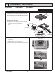
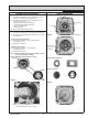
6. Removing the electrical box
(1) Remove the electrical box cover (See Photo 1 and 2.)
and the connectors (Refer to procedure 5.).
(2) Remove the electrical box fixing screws (M5 × 10: 2
screws). (See Photo 3.)
<Electrical parts in the electrical box>
• Terminal block for earth and reactor
• Indoor controller board
• Thermistor (TH)
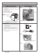
(3)
Remove the electrical box (2 hooks).
Photo 5
Photo 6
< Nut and square washer >
< Nut and washer >
Photo 8
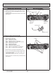
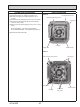
7. Removing the turbo fan
(1) Remove the electrical box. (See Photo 3 and refer to 6.)
(2) Remove the bell mouth (tapping screw 4×10: 2 screws).
(See Photo 5.)
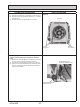
<
With nut and square washer
>
(3) Remove the nut (M8 × 1) and a square washer.
(See Photo 6 and 7.)
(4) Remove the turbo fan.
<
With nut and washer
>
(3) Remove the nut (M8 × 1) and a washer.
(See Photo 6 and 7.)
(4) Remove the turbo fan.
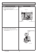
Note 1: When assembling the turbo fan, attach it so that
it's tabs fit the holes of washer.
Note 2: Nut tightening torque: 4.5 ± 0.5 Nm.
Photo 7
Electrical box
Bell mouth xing screws
Bell mouth
Turbo fan
Nut and square
washer or nut
and washer
Turn this way to tighten.
Turn this way to loosen.
(The same directions as the fan rotation.)
hooks
Turbo fan
Washer
tabs
holes
41
OCH640D
Be careful when removing heavy parts.