
Indoor Service Manual

33
OCH640D
SW1
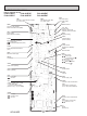
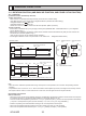
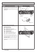
Setting by the DIP switch and jumper wire
Functions
Jumper wire
Model
settings
Capacity
settings
Pair number
setting with
IR wireless
remote
controller
Remarks
SW2
J41
J42
0
1
2
3 to 9
Wireless remote
controller setting
Control PCB setting
J41 J42
<Initial setting>
IR wireless remote controller: 0
Control PCB: (for both J41 and J42)
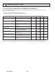
4 pair number settings are supported.
The pair number settings of the wireless remote
controller and indoor control PCB (J41/J42) are
given in the table on the left.
(' ' in the table indicates the jumper wire is disco-
nnected.)
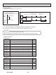
Jumper wire ( : Short : Open)
1 2 3 4 5 6
ON
OFF
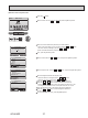
MODEL
Service
PLA-A·EA7
Service
PLA-A12EA7
MODEL
ON
OFF
1 2 3 4 5
Service
PLA-A30EA7
MODEL
ON
OFF
1 2 3 4 5
PLA-A18EA7
ON
OFF
1 2 3 4 5
PLA-A36EA7
ON
OFF
1 2 3 4 5
PLA-A24EA7
ON
OFF
1 2 3 4 5
PLA-A42EA7
ON
OFF
1 2 3 4 5
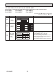
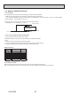
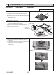
9-8. FUNCTIONS OF DIP SWITCH AND JUMPER WIRE
Each function is controlled by the DIP switch and the jumper wire on indoor controller board.
PLA-A12EA7 PLA-A18EA7 PLA-A24EA7
PLA-A30EA7 PLA-A36EA7 PLA-A42EA7
The black square (■) indicates a switch position.