
Indoor Installation Manual


7
6. Electrical work
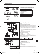
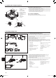
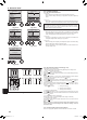
6.1. Indoor unit (Fig. 6-1)
1. Loosen the two screws securing the electrical wiring service panel, and then turn
the electrical wiring service panel. [Fig. 6-1 1]
2. Loosen the two screws securing the electrical box cover, then slide the electrical
box cover. [Fig. 6-1 2]
3. Passthepowercable,indoor/outdoorunitconnectingcableandearthcable
through the wiring entries given in the diagram. [Fig. 6-1 3]
Putthesheathportionofthepowercableandindoor/outdoorconnectingcable
into electrical box.
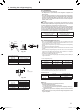
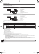
Useroundcrimpedterminalsfortheindoor-outdoorconnectionterminalboard
and the optional power supply terminal kit. [Fig. 6-2]
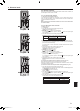
If you cannot use round crimped terminals, following the procedure in Fig. 6-4 to
6-6.
Refer to 6.1.1. for the connection.
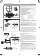
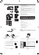
4. Pass and wire the remote controller cable through the wiring entries given in the
diagram. [Fig. 6-1 4, Fig. 6-3]
Refer to 6.1.1. for the connection.
• Donotallowslackeningoftheterminalscrews.
Screw tightening torque
Tightening torque (N·m, ft·lbs)
Remote controller terminal board 1.2 ± 0.1, 0.9 ± 0.1
Indoor-outdoor connection terminal board 1.6 ± 0.1, 1.2 ± 0.1
Earth cable 1.6 ± 0.1, 1.2 ± 0.1
• Leaveexcesscablesothattheelectricalboxcanbesuspendedbelowtheunit
duringservicing(approx.50to100mm,1-31/32to3-15/16inch).
A
Electrical wiring service panel
B Screw
C Electrical box cover
D Temporary hook for electrical box cover
E Screw
F Slide direction of the electrical box cover
GEntryforpowercableandindoor/outdoorunitconnectingcable
H Secure with the cable strap.
I Earth cable
JIndoor/outdoorunitconnectingterminal
K Electrical wiring service panel (remote controller)
L Entry for wired remote controller
M Wired remote controller terminal
N Secure with the cable strap.
Caution:
• Wiringforremotecontrollercableshallbeapart(50mm,2inchormore)from
powersourcewiringsothatitisnotinuencedbyelectricnoisefrompower
source wiring.
Fig. 6-1
Fig.6-3
Fig. 6-2
[1]
[2]
[3]
[4]
B
E
A
C
D
F
G
I
L
H
J
K
M
N
15/32
19/32
25/64
Be sure to connect the remote
controller cable (0.3 mm
2
, AWG22)
to the locations shown in the
diagram.
• Ifthe cables have the samediameter,
insert them into the cut outs on both sides.
• Ifthecableshavedifferentdiameters,in-
sert them on one side into separate spaces
with one cable positioned above the other.
Secure with a band 4 (small)
at the location shown in the
diagram
<When wiring two indoor-outdoor connection cables>
(Remote controller
cable retainer)
Cable strap
WARNING
• Connectingtwowiresononesideisprohib-
ited.
• Connectingthreewiresormoretothesame
terminal is prohibited.
• Connectingwireswithdifferentdiametersis
prohibited.
When using a single cable, a round crimped terminal or other
terminal work is prohibited.
Cut outs
Insulating sleeve
Electrical cable
Round crimped terminal
Fig.6-5 Fig. 6-6
15/32
Fig.6-4
(inch) (inch)
• TheU-shapedgrooveopensifyoupushthescrewheadafterthescrewisloosened.
BH79D659K02.indb 7 2017/05/22 17:25:29