
Indoor Installation Manual


6
B
C
1/4
7
45/64
A
A
H
H
G
G
D E
C K
F
F
1-
3/16
1-
3/16
9/32
C
J
I
1
A
B
K
B
F
D
F F
H
I
G
E
D
D
L
M
C
F
J
2
3
A
D
E
C
B
F
B, C
F
G
H
I
J
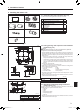
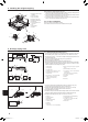
Heatinsulationforrefrigerantpipes(Fig.4-3)
1 Wrap the enclosed large-sized pipe cover around the gas pipe, making sure that
the end of the pipe cover touches the side of the unit.
2 Wrap the enclosed small-sized pipe cover around the liquid pipe, making sure that
the end of the pipe cover touches the side of the unit.
3 Secure both ends of each pipe cover with the enclosed bands. (Attach the bands
20mm,25/32inchfromtheendsofthepipecover.)
4.3.Fortwincombination
Refer to the outdoor unit installation manual.
Some outdoor units cannot be used in a simultaneous twin system.
4. Installingtherefrigerantpiping
5. Drainagepipingwork
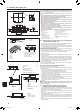
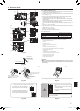
5.1.Drainagepipingwork(Fig.5-1)
• Theindoorpartsofthedrainpipeshouldbewrappedwithpolyethylenefoaminsula-
tionmaterials(specicgravityof0.03,thicknessof9mm,23/64inchormore).
• UseVP25(O.D.ø32mm,1-1/4inchPVCTUBE)fordrainpipingandprovide1/100
or more downward slope.
• BesuretoconnectthepipingjointsusingaPVCtypeadhesive.
• Observethegureforpipingwork.
• Usetheincludeddrainhosetochangetheextractiondirection.
• Whenperformingthedrainagepipingwork,besuretousethesupportmetalholders.
If a load is applied to the drain socket that damages the hose or causes the hose
to become detached, water leakage may result.
A Refrigerant pipe and heat
insulation
B Pipe cover (large)
C Pipe cover (small)
D Refrigerant pipe (gas)
E Refrigerant pipe (liquid)
F Band (large)
G Cross-sectional view of
connection
H Pipe
I Heat insulation
J Squeeze
Fig.4-3
Fig.5-1
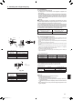
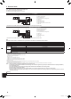
Fig.5-2
Max. 65ft
Max. 6 inch
5 to 7 ft
(inch)
1
Correct piping
2 Wrong piping
3 Grouped piping
AInsulation(9mm,23/64inchormore)
BDownwardslope(1/100ormore)
C Support metal
DO.D.ø32mm,1-1/4inchPVCTUBE
E Make it as large as possible
(about10cm,3-15/16inch)
F Main unit
G Make the piping size large for grouped
piping.
HDownwardslope(1/100ormore)
IO.D.ø38mm,1-1/2inchPVCTUBEfor
grouped piping
(9mm,23/64inchormoreinsulation)
JUpto85cm,33-7/16inch
K Air bleeder
L Raised
M Odor trap
1. Connect the drain socket (supplied with the unit) to the drain port. (Fig. 5-2)
(FixthetubeusingPVCadhesivethensecureitwithaband.)
2.Installalocallypurchaseddrainpipe(PVCpipe,O.D.ø32mm,1-1/4inch).
(FixthepipeusingPVCadhesivethensecureitwithaband.)
3.Checkthatdrainowssmoothly.
4. Insulate the drain port and socket with insulating material, then secure the material
with a band. (Both insulating material and band are supplied with the unit.)
5.Insulatethetubeandpipe.(PVCpipe,O.D.ø32mm,1-1/4inch)
A
Main unit
B Insulating material
C Band (large)
D Drain port (transparent)
E Insertion margin
F Matching
G Drain pipe
(O.D.ø32mm,1-1/4inchPVCTUBE)
H Insulating material (purchased locally)
ITransparentPVCpipe
JO.D.ø32mm,1-1/4inchPVCTUBE
(Slope1/100ormore)
K Drain socket
BH79D659K02.indb 6 2017/05/22 17:25:28