
Indoor Installation Manual


4
A
B
A
A
C
D
D
E
F
C
C
G
B
B
26
31-5/16
A
B
1 2
H
I
J
C
D E
F
G
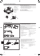
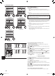
3. Installingtheindoorunit
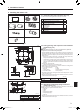
3.4.Branchductholeandfreshairintakehole(Fig.3-4)
At the time of installation, use the duct holes (cut out) located at the positions shown
in Fig. 3-4, as and when required.
• Afreshairintakeholefortheoptionalmultifunctioncasementcanalsobemade.
Note:
• Theguremarkedwith*inthedrawingrepresentthedimensionsofthemain
unitexcludingthoseoftheoptionalmultifunctioncasement.
• When installingtheoptional multifunctioncasement, add135mm, 5-5/16
inchtothedimensionsmarkedonthegure.
• Wheninstallingthebranchducts,besuretoinsulateadequately.Otherwise
condensation and dripping may occur.
• Wheninstallingthefreshairintakehole,besuretoremovetheinsulatorP
that is pasted on the indoor unit.
• Whenexternalairisinputdirectlythroughthemainunit,intake-airvolume
shouldbe5%orlessofindoorunitairvolume.
• Toinputtheexternal air, theduct fanand dustcollecting lterto prevent
drawing in dust and other particles are necessary.
For details, see “Fresh air intake volume & static pressure characteristics”
in the P series DATA BOOK.
• Whenexternalairisinputintothemainunit,theoperationnoisecanbelarger.
A Branch duct hole Iø175mm,ø6-7/8inchburringholepitch
B Main unit J Fresh air intake hole diagram
C Fresh air intake hole K 3-4×10 tapping screws
D Drain pipe Lø125mm,ø4-15/16inchburringholepitch
E Refrigerant pipe Mø100mm,ø3-15/16inchcutouthole
F Branch duct hole diagram N Ceiling
(view from either side)
O
Detailedgureofremovingtheinsulator
G 14-4×10 tapping screws
P Insulation
Hø150mm,ø5-7/8inchcutouthole
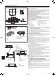
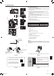
3.5. Suspension structure(Givesiteofsuspension
strongstructure)(Fig.3-5)
• Theceilingworkdiffersaccordingtotheconstructionofthebuilding.Buildingcon-
structors and interior decorators should be consulted for details.
(1) Extent of ceiling removal: The ceiling must be kept completely horizontal and the
ceiling foundation (framework: wooden slats and slat holders) must be reinforced
in order to protect the ceiling from vibration.
(2) Cut and remove the ceiling foundation.
(3) Reinforce the ends of the ceiling foundation where it has been cut and add ceiling
foundation for securing the ends of the ceiling board.
(4) When installing the indoor unit on a slanted ceiling, attach a pillar between the
ceiling and the grille and set so that the unit is installed horizontally.
1 Wooden structures
• Usetiebeams(singlestoriedhouses)orsecondoorbeams(2storyhouses)as
reinforcing members.
• Woodenbeamsforsuspendingairconditionersmustbesturdyandtheirsidesmust
beatleast6cm,ø2-3/8inchlongifthebeamsareseparatedbynotmorethan90
cm,ø35-7/16inchandtheirsidesmustbeatleast9cm,ø3-9/16inchlongifthe
beamsareseparatedbyasmuchas180cm,70-7/8inch.Thesizeofthesuspen-
sionboltsshouldbeø10(3/8").(Theboltsdonotcomewiththeunit.)
2 Ferro-concrete structures
Secure the suspension bolts using the method shown, or use steel or wooden hang-
ers, etc. to install the suspension bolts.
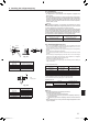
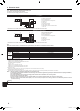
3.6.Unitsuspensionprocedures(Fig.3-6)
Suspend the main unit as shown in the diagram.
Figures given in parentheses represent the dimensions in case of installing optional
multi function casement.
1. In advance, set the parts onto the suspension bolts in the order of the washers
(with insulation), washers (without insulation) and nuts (double).
• Fitthewasherwithcushionsothattheinsulationfacesdownward.
• Incaseofusingupperwasherstosuspendthemainunit,thelowerwashers(with
insulation) and nuts (double) are to be set later.
2. Lift the unit to the proper height of the suspension bolts to insert the mounting
plate between washers and then fasten it securely.
3. When the main unit cannot be aligned against the mounting hole on the ceiling, it
is adjustable owing to a slot provided on the mounting plate.
• MakesurethatAisperformedwithin17-22mm,11/16to3/4inch.Damagecould
result by failing to adhere to this range. (Fig. 3-7)
Caution:
Usethetophalfoftheboxasaprotectivecovertopreventdustordebrisfrom
getting inside the unit prior to installation of the decorative cover or when ap-
plying ceiling materials.
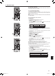
3.7.Conrmingthepositionofmainunitand
tighteningthesuspensionbolts(Fig.3-8)
• Usingthegaugeattachedtothegrille,ensurethatthebottomofthemainunitis
properlyalignedwiththeopeningoftheceiling.Besuretoconrmthis,otherwise
condensation may form and drip due to air leakage, etc.
• Conrmthatthemainunitishorizontallylevelled,usingaleveloravinyltubelled
with water.
• Aftercheckingthepositionofthemainunit,tightenthenutsofthesuspensionbolts
securely to fasten the main unit.
• Theinstallationtemplate(topofthepackage)canbeusedasaprotectivesheet
to prevent dust from entering the main unit when the grilles are left unattached for
a while or when the ceiling materials are to be lined after installation of the unit is
nished.
* Asforthedetailsoftting,refertotheinstructionsgivenontheInstallationtemplate.
(top of the package)
Fig.3-4
Fig.3-5
Fig.3-6
Fig.3-7
Fig.3-8
D Ceiling
E Rafter
F Beam
G Roof beam
HUseinsertsratedat100-150kg,
221-331 lbs each (procure locally)
ISuspensionboltsM10(3/8”)
(procure locally)
J Steel reinforcing rod
A Main unit
B Grille
C Pillar
A Suspension bolt
B Ceiling
C Nut
D Washer (with insulation)
E Mounting plate
F Washer (without insulation)
G Check using the Installation gauge
A Main unit
B Ceiling
C Gauge
D Ceiling opening dimensions
A Main unit
B Ceiling
C Installation template
(top of the package)
Min.1-3/16
A
C
B
(inch)
(inch)
4-1/8(9-7/16)
11/16
+3/16
0
11/16
+3/16
0
A
B
C
D
P
F
O
E
A
A
I
F
70°
3-1/2
G
H
*6-9/16
*6-1/8
3-15/16 3-15/16
3-1/2
3-15/16
5-1/8
13-3/4
K
J
M
*6-1/4
N
120°
120°
L
BH79D659K02.indb 4 2017/05/22 17:25:27