
Indoor Installation Manual

17
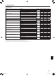
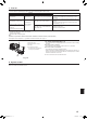
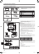
H
A
D
J
A Main unit
B Corner of drain pipe
C Claw on the main unit
D Grille 1
E Hole on the grille
F Hook for temporary installation
G Screw with captive washer
H Ceiling surface
J No gap
K Adjust the nut of main unit using a wrench,
etc.
Fig.9-8
Fig.9-10
Fig. 9-9
Fig. 9-7
Fig. 9-6
9. Installing the grille
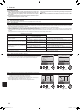
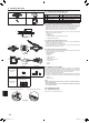
F
E
D
A
B
C
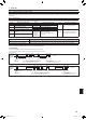
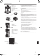
C
D
G
K
C
B
A
D
G
C
F
E
B
A
A Clamp of the main unit
B Electrical box
C Lead wires of the grille
DCNVconnectoronthecontrollerboard
A CN4Z on the controller board
B CN5Y on the controller board
C Lead wire of i-see Sensor corner panel
D Clamp
E Hole of grille (Pass the lead wire.)
F Screw 3
G i-see Sensor corner panel 4
< The grille temporary installed >
9.4.2.Temporaryinstallationofthegrille(Fig.9-6)
• Jointhecornerofdrainpipeonthemainunitwiththecornerwithholeonthegrille
and put them together temporarily by hanging the hook of the grille to the claw of
the main unit.
9.4.3. Fixingthegrille
• Bytighteningthepre-installedscrews,xthegrilleontothemainunit.(Fig.9-6)
Note:
Make sure there is no gap between the main unit and the grille or between the
grille and the ceiling surface. (Fig. 9-7)
If there is a gap between the grille and the ceiling:
With the grille attached, slightly adjust the installation height of the main unit and
clear the gap.
Caution:
• Whentighteningthescrew,makesurethatthetighteningtorqueis2.8N∙m
to3.6N∙m,2.1to2.6ft∙lbs.Neveruseanimpactscrewdriver.
• Aftertighteningthescrew,conrmthatthetwogrillehooks(Fig.9-6)are
latched onto the hooks on the main unit.
9.4.4. Wireconnection(Fig.9-8)
• Loosethe2screwsxingtheelectricalboxcoveronthemainunit,andslidethe
cover to open.
• Routetheleadwirefromsideoftheelectricalbox.
• Makesuretoconnectaconnectorforvanemotor(white,20poles)toCNVcon-
nector (white) on the controller board of the main unit.
• Leadwiresthatleadoffthegrillemustbeheldtogetherwithoutslackusingaclamp
into the electrical box.
9.4.5. Installationofi-seeSensorcornerpanel(Fig.9-9)
• Routetheleadwirefromthesideofelectricalbox.
• Routetheleadwireconnector(white,4polesandwhite,5poles)ofthei-seeSensor
corner panel 4 from the side of the electrical box on the main unit and connect to
the connector CN4Z and CN5Y on the controller board.
• Theremainingleadwireofi-seeSensorcornerpanelmustbeheldtogetherwithout
slack using the clamp into the electrical box.
• Putthecoverbackontheelectricalboxwith2screws.
Note:
Make sure wires are not caught in the electrical box cover.
• Thei-seeSensorcornerpanelshouldbexedontothegrille1 with screw 3.
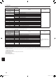
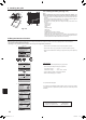
* If the position of the i-see Sensor was changed from default position (Position 3)
to the other position, change the function settings. (Refer to page 11 and Fig. 9-10)
• Thei-seeSensorcornerpanelcannotinstalledonthedrainpipesideforthemain
unit. (Refer to Fig. 9-10)
Position 1:(Airoutletidenticationmarks□/□□□□)
Position 2:(Airoutletidenticationmarks□/□□)
Position 3:Defaulti-seeSensorposition(Airoutletidenticationmarks□□/□□□)
Position 1
Position 2
Position 3
Refrigerant pipe
Prohibited installation
position
Drain pipe
BH79D659K02.indb 17 2017/05/22 17:25:35