
Indoor Installation Manual

16
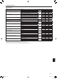
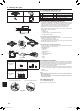
9.1. Checking the contents (Fig. 9-1)
• Thiskitcontainsthismanualandthefollowingparts.
Accessory name Q’ty Remarks
1
Grille
1
950×950(mm),37-3/8×37-3/8(inch)
2
Installation gauge
1
(Divided into 4 parts)
3
Screw (4 × 16)
1
ForPLP-40EAU,PLP-40EAEU
4
i-see Sensor corner panel
1
ForPLP-40EAEU
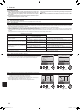
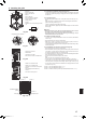
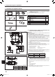
9.2. Preparing to attach the grille (Fig. 9-2)
• Withthegauge2 supplied with this kit, adjust and check the positioning of the main
unit relative to the ceiling surface. If the main unit is not properly positioned relative
to the ceiling surface, it may allow air leaks or cause condensation to collect.
• Makesurethattheopeningintheceilingiswithinthefollowingtolerances:
860 × 860-910 ×910mm,33-7/8×33-7/8to35-13/16×35-13/16inch
• MakesurethatAisperformedwithin17-22mm,11/16to7/8inch.Damagecould
result by failing to adhere to this range.
A Main unit
B Ceiling surface
C Installation gauge 2 (inserted into the main unit)
D Ceiling opening dimensions
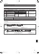
9.2.1. Removingtheintakegrille(Fig.9-3)
• Slidetheleversinthedirectionindicatedbythearrows1 to open the intake grille.
• Unlatchthehookthatsecuresthegrille.
* Do not unlatch the hook for the intake grille.
• Withtheintakegrilleinthe“open”position,removethehingeoftheintakegrille
from the grille as indicated by the arrows 2.
9.2.2. Removingthecornerpanel(Fig.9-4)
• Loosethe4screwsonthecorner.Slidethecornerpanelinthedirectionofthearrow
1inthegureandremovethecornerpanel.
[Fig.9-3][Fig.9-4]
A Intake grille
B Grille 1
C Intake grille levers
D Grille hook
E Hole for the grille’s hook
F Corner panel
G Screw
H Detail
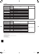
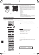
9.3.Selectionofairoutlets
For this grille the discharge direction is available in 11 patterns. Also, by setting the
remotecontrollertotheappropriatesettings,youcanadjusttheair-owandspeed.
Select the required settings from the Table 1 according to the location in which you
want to install the unit. (More than two directions must be selected.)
1) Decide on the discharge direction pattern.
2) Be sure to set the remote controller to the appropriate settings according to the
number of air outlets and the height of the ceiling on which the main unit will be
installed.
(Refer to page 11.)
Notes:
• Whenchangingthenumberofdirections,youneedanairoutletshutterplate,
which is optional part.
• Donotselect2directionsinahotandhumidenvironment.(Dewformation
or dew drop may result.)
9.4.Installingthegrille
9.4.1. Preparations(Fig.9-5)
Makesuretoip2hooksonthegrilleup.
9. Installing the grille
A
D
A=11/16
+3/16
0
B
C
Fig.9-3
Fig. 9-2
Fig.9-4
Fig. 9-1
Fig.9-5
4-directional 3-directional
Blowout direction
patterns
1 pattern: initial setting
4 patterns:
one air outlet fully closed
2-directional
Blowout direction
patterns
6 patterns:
2 air outlet fully closed
Table 1
C
A
B
E
D
2
2
F
B
1
F
G
H
G
<Hook is in the lowered position><Hook is in the raised position>
1 2
3 4
BH79D659K02.indb 16 2017/05/22 17:25:32