
Indoor Installation Manual


10
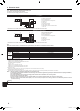
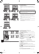
6.3.Functionsettings
6.3.1. Bywiredremotecontroller
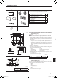
1 (Fig. 6-10)
• Select “Service” from the Main menu, and press the [SELECT] button.
• Select“Functionsettings”withthe[F1]or[F2]button,andpressthe[SELECT]
button.
2 (Fig. 6-11)
• Settheindoorunitrefrigerantaddressesandunitnumberswiththe[F1] through
[F4] buttons, and then press the [SELECT]buttontoconrmthecurrentsetting.
<Checking the Indoor unit No.>
When the [SELECT] button is pressed, the target indoor unit will start fan operation.
If the unit is common or when running all units, all indoor units for the selected
refrigerant address will start fan operation.
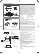
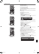
3 (Fig. 6-12)
• Whendatacollectionfromtheindoorunitsiscompleted,thecurrentsettings
appear highlighted. Non-highlighted items indicate that no function settings are
made.Screenappearancevariesdependingonthe“UnitNo.”setting.
4 (Fig. 6-13)
• Usethe[F1] or [F2] button to move the cursor to select the mode number, and
change the setting number with the [F3] or [F4] button.
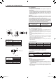
5 (Fig. 6-14)
• Whenthesettingsarecompleted,pressthe[SELECT] button to send the setting
data from the remote controller to the indoor units.
• Whenthetransmissionissuccessfullycompleted,thescreenwillreturntothe
Function setting screen.
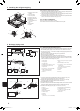
6. Electrical work
F1 F2 F3 F4
Service menu
Cursor
Main menu:
Test run
Input maintenance info.
Function setting
Check
Self check
F1 F2 F3 F4
Function setting
Cursor Address
Monitor:
Ref. address
Unit No.
Grp./1/2/3/4/All
Fig.6-10 Fig. 6-11
F1 F2 F3 F4
Function setting
Cursor Cursor
Request:
Ref. address
Mode 1
Mode 2
Mode 3
Mode 4
Grp.
F1 F2 F3 F4
Function setting
Cursor Cursor
Request:
Ref. address
Mode 7
Mode 8
Mode 9
Mode 10
Unit # 1
Fig. 6-12 Fig.6-13
F1 F2 F3 F4
Function setting
Ref. address
Sending data
Grp.
Fig.6-14
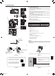
6.3.2. ByIRwirelessremotecontroller(Fig.6-15)
Changing the power voltage setting
• Besuretochangethepowervoltagesettingdependingonthevoltageused.
1 Going to the function select mode
Press the
CHECK
button F twice continuously.
(Start this operation from the status of IR wireless remote controller display turned off.)
CHECK
is lit and “00” blinks.
Press the
temp button C once to set “50”. Direct the IR wireless remote controller
toward the receiver of the indoor unit and press the
h
button A.
2 Setting the unit number
Press the
temp buttons C and D to set the unit number “00”. Direct the IR wireless
remote controller toward the receiver of the indoor unit and press the
min
button B.
3 Selecting a mode
Enter 04 to change the power voltage setting using the
temp buttons C and D.
Direct the IR wireless remote controller toward the receiver of the indoor unit and
press the
h
button A.
Current setting number: 1 = 1 beep (one second)
2 = 2 beeps (one second each)
3 = 3 beeps (one second each)
4 Selecting the setting number
Usethe
temp buttons C and D to change the power voltage setting to 01 (240
V).DirecttheIRwirelessremotecontrollertowardthesensoroftheindoorunitand
press the
h
button A.
5 To select multiple functions continuously
Repeat steps 3 and 4 to change multiple function settings continuously.
6 Complete function selection
Direct the IR wireless remote controller toward the sensor of the indoor unit and
press the
button E.
Note:
Whenever changes are made to the function settings after installation or main-
tenance, be sure to record the changes with a mark in the “Setting” column of
the Function table.
6.3.3. Functionsettingontheremotecontroller
Refer to the appropriate operation manual included with each remote controller.
Fig. 6-6
CHECK
CHECK
ON/OFF TEMP
FAN
VANE
TEST RUN
AUTO STOP
AUTO START
h
min
LOUVER
MODE
CHECK
RESETSET CLOCK
CHECK
CHECKCHECK
Mode number
Setting number
Refrigerant address
Unit number
PAR-21MAA
ON/OFF
FILTER
CHECK
OPERATION
CLEAR
TEST
TEMP.
MENU
BACK DAY
MONITOR/SET
CLOCK
ON/OFF
Fig.6-15
BH79D659K02.indb 10 2017/05/22 17:25:30