
Service Manual


95
OPERATING PROCEDURE
PHOTOS
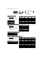
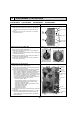
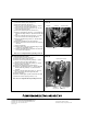
11. Removing bypass valve coil (SV) and bypass valve
(1) Remove the service panel. (See Figure 1.)
(2) Remove the top panel. (See Figure 1.)
(3) Remove 3 right side panel fixing screws (5 × 10) in the
rear of the unit and remove the right side panel.
(4) Remove the bypass valve solenoid coil fixing screw (M5
× 6).
(5) Remove the bypass valve coil by sliding the coil upward.
(6) Disconnect the connector SV2 (blue) on the controller cir-
cuit board in the electrical parts box.
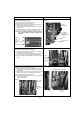
(7) Recover refrigerant.
(8) Remove the welded part of bypass valve.
Note 1: Recover refrigerant without spreading it in the
air.
Note 2: The welded part can be removed easily by
removing the right side panel.
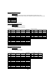
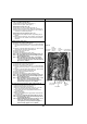
12. Removing the reactor (DCL) and capacitor (CE)
(1) Remove the service panel. (See Figure 1.)
(2) Remove the top panel. (See Figure 1.)
(3) Remove the electrical parts box. (See Photo 3.)
<Removing the reactor>
(4) Remove 4 reactor fixing screws (4 × 10) and remove the
reactor.
<Removing the capacitor>
(4) Remove 2 capacitor band fixing screws (4 × 10) and
remove the capacitor.
w The reactor and capacitor are attached to the rear of the
electrical parts box.
Capacitor band
fixing screws
Photo 11
Reactor
fixing
screws
Reactor
fixing
screws
Reactor
(DCL)
Electrical parts box
Capacitor (CE)
Photo 10
Bypass valve
Thermistor
<Outdoor pipe>
(TH33)
Bypass valve coil (SV)
Bypass valve
coil fixing screw
Replace filter