
Indoor Installation Manual

8
Indoor unit model PLA-A12EA7 PLA-A18EA7 PLA-A24EA7 PLA-A30EA7 PLA-A36EA7 PLA-A42EA7
Minimum circuit ampacity 1 A 1 A 1 A 1 A 2 A 2 A
Maximum ration of overcurrent protective device 15 A
Wiring
Wire No.
× size
Indoor unit-Outdoor unit *1 3 × AWG14 (polar)
Indoor unit earth 1 × Min. AWG14
Remote controller-Indoor unit *2 2 × AWG22 (Non-polar, unshielded)
Circuit
rating
Indoor unit-Outdoor unit S1-S2 *3 208/230VAC
Indoor unit-Outdoor unit S2-S3 *3 24VDC
Wired remote controller-Indoor unit *3 12VDC
6. Electrical work
* AfxlabelAthatisincludedwiththemanualsneareachwiringdiagramfortheindoorandoutdoorunits.
Note:
Some units cannot be used in a simultaneous twin system. Refer to the outdoor unit installation manual for details.
*1. <For 35-140 outdoor unit application>
Max. 45 m, 148 ft
If AWG13 (2.5 mm
2
) used, Max. 50 m, 165 ft
If AWG13 (2.5 mm
2
) used and S3 separated, Max. 80 m, 263 ft
<For200/250outdoorunitapplication>
Max. 18 m, 59 ft
If AWG13 (2.5 mm
2
) used, Max. 30 m, 99 ft
If AWG11 (4 mm
2
) used and S3 separated, Max. 50 m, 165 ft
If AWG9 (6 mm
2
) used and S3 separated, Max. 80 m, 263 ft
*2. Max. 500 m, 1640 ft
(When using 2 remote controllers, the maximum wiring length for the remote controller cables is 200 m, 656 ft.)
*3.TheguresareNOTalwaysagainsttheground.
S3terminalhas24VDCagainstS2terminal.HoweverbetweenS3andS1,theseterminalsarenotelectricallyinsulatedbythetransformerorotherdevice.
Notes: 1. Wiringsizemustcomplywiththeapplicablelocalandnationalcode.
2.
Powersupplycordsandindoorunit/outdoorunitconnectingcordsshallnotbelighterthanpolychloroprenesheathedexiblecord.(Design60245IEC57)
3.Usecoppersupplywires.
4.Usewiresrated300Vormoreforthepowersupplycablesandtheindoorunit/outdoorunitconnectingcables.
5. Installanearthlongerthanothercables.
6. Indoorandoutdoorconnectingwireshavepolarities.Makesuretomatchtheterminalnumber(S1,S2,S3)forcorrectwirings.
7. Wiringforremotecontrollercableshallbeapart(5cm,2inchormore)frompowersourcewiringsothatitisnotinuencedbyelectricnoisefrom
power source wiring.
Neversplicethepowercableortheindoor-outdoorconnectioncable,otherwiseitmayresultinasmoke,areorcommunicationfailure.
Warning:
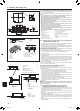
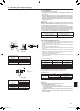
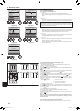
6.1.1. Indoor unit power supplied from outdoor unit
The following connection patterns are available.
The outdoor unit power supply patterns vary on models.
S1
S2
L1
L2
GR
1
2
S1
S2
S3
S3
A B C
D
E
F
G
I
H
CN105
RED
S1
S2
1
2
S1
S2
S3
1
2
S1
S2
S3
S3
D
E
F
G
G
E
L1
L2
GR
A B C
* AfxlabelAthatisincludedwiththemanualsneareachwiringdiagramfortheindoorandoutdoorunits.
A Outdoor unit power supply
B Earth leakage breaker
C Wiring circuit breaker or isolating switch
D Outdoor unit
E Indoor earth
F Wired remote controller
G Indoor controller board
H Radio frequency interface for RF thermostat
I Indoor unit
Only for wired remote controller
A Outdoor unit power supply
B Earth leakage breaker
C Wiring circuit breaker or isolating switch
D Outdoor unit
E Indoor earth
F Wired remote controller
G Indoor unit
Simultaneous twin system
1:1 System
BH79D659K02.indb 8 2017/05/22 17:25:29