
Indoor Service Manual

OPERATING PROCEDURE PHOTOS/FIGURES
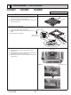
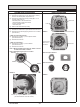
10. Removing the drain pan
(1) Remove the electrical box. (See photo 3 and refer to 6.)
(2) Remove the bell mouth (tapping screw 4×10 : 2 screws).
(See Photo 5.)
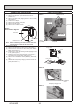
(3) Remove the drain pan (screw M5×10: 4 screws).
Photo 12
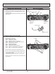
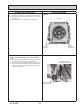
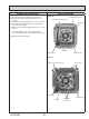
11. Removing the pipe temperature thermistor/liquid (TH2)
and the condenser/evaporator temperature thermistor
(TH5)
(1) Remove the drain pan (Refer to procedure 10.) and loos-
en the 2 clamps of the coil plate. (See Photo 9.)
(2) Remove the coil plate (tapping screw 4×10: 2 screws).
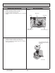
(3) Disconnect the pipe temperature thermistor/liquid (TH2)
and the condenser/evaporator temperature thermistor
(TH5) from the holder.
Photo 13
Drain pan
Drain pan
xing screws
Drain pan
xing screws
Condenser/evaporator
temperature thermistor (TH5)
Pipe temperature/liquid
thermistor (TH2)
43
OCH640D