
Indoor Service Manual

OPERATING PROCEDURE PHOTOS/FIGURES
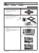
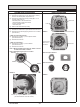
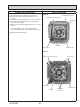
8. Removing the fan motor (MF)
(1) Remove the turbo fan. (See Photo 6 and refer to
procedure 7.)
(2) Remove the lead cover (tapping screw 4×10: 2 screws).
(See Photo 9.)
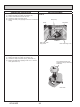
(3) Loosen the 2 clamps.
(4) Remove the 3 washer nuts (M5).
(5) Remove the fan motor.
(6) Remove the 3 rubber mounts.
Figure 3
Cross section diagram
Note: When re-attaching the motor mount, make sure
that the thicker end faces the motor shaft.
Photo 9
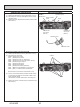
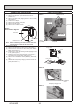
9. Removing the panel
(1) Remove the electrical box fixing cover. (See Photo 1.)
(2) Disconnect the connector for vane motor (CNV: White).
(Refer to procedure 5.)
(3) Loosen the 4 corner panel fixing screws (tapping screw
4×16). (See Figure 4.)
(4) Slide the corner panel to the direction of the arrow 1,
and remove the corner panel. (See Figure 4.)
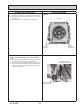
(5) Remove the 4 installation screws (M5×28). (See Photo
10.)
(6) Release the 2 temporary hanging hooks to remove the
grille. (See Photo 11.)
Figure 4
Corner panel
①
①
Corner panel
Close-up
Screw
Grille
Photo 10
Photo 11
Installation
screw
Temporary hanging hook
Nut washer
Rubber mount
Fan motor
Clamp
(2 points)
Lead cover
Coil plate
Lead cover
xing screws
Fan motor
Nuts and washers
Rubber mounts
42 43
OCH640D