
Indoor Service Manual

31
OCH640D
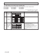
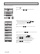
<Thermistor characteristic graph>
Room temperature thermistor(TH1)
Pipe temperature thermistor/liquid(TH2)
Condenser/evaporator temperature
thermistor(TH5)
Thermistor R0=15 k" ± 3%
Fixed number of B=3480 ± 2%
t(:)Rt=15exp { 3480( ) }
T(˚F)Rt=15exp { 3480( ) }
32˚F [0:] 15 k"
50˚F [10:] 9.6 k"
68˚F [20:] 6.3 k"
77˚F [25:] 5.4 k"
86˚F [30:] 4.3 k"
104˚F [40:] 3.0 k"
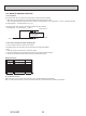
Thermistor for
lower temperature
1
273+t
1
273
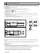
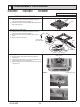
9-6-1. Thermistor
Notes
· High voltage is applied to the connecter (CNMF) for the fan motor. Pay attention to the service.
· Do not pull out the connector (CNMF) for the motor with the power supply on.
(It causes trouble of the indoor controller circuit
board and fan motor.)
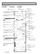
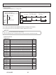
Self check
Symptom : The indoor fan cannot rotate.
No
Fail
Fail
Wiring contact check
Contact of fan motor connector (CNMF)
Check the fuse (FUSE) on indoor
controller board.
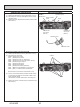
Power supply check (Remove the connector (CNMF))
Measure the voltage in the indoor controller circuit
board.
TEST POINT 1 : VDC (between 1 (+) and 4 (−) of the fan connector): VDC 294–325 V DC
TEST POINT 2 : VCC (between 5 (+) and 4 (−) of the fan connector): VCC 15 V DC
Correct wiring.
Replace the drain pump (DP).
Replace the indoor controller board.
Replace the defective fan motor.
Replace the indoor controller board (I.B).
Replace the defective fan motor (MF).
Replace the indoor
controller board.
Replace the defective fan motor.
Is the voltage normal?
Is there contact failure?
Yes
1
2
Yes
No
Did the fuse blow?
Check the drain pump (DP).
Is the resistance between
terminals normal?
No
Yes
Yes
No
Check the operation of fan. Complete.
Complete.
Yes
OK
Check the operation.
OK
Check method of DC fan motor (fan motor/indoor controller circuit board)
9-6-2. DC fan motor (fan motor/indoor controller board)
0
10
20
30
40
50
−
20
−
10 0 10 20 30 40 50
−
4
−
14 32 50 68 86 104122
:
°F
Temperature
Resistance (k")
<Thermistor for lower temperature>
1
273+
1
273
T-32
1.8