
Indoor Service Manual

30 31
OCH640D
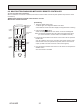
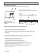
9-6. HOW TO CHECK THE PARTS
PLA-A12EA7 PLA-A18EA7 PLA-A24EA7
PLA-A30EA7 PLA-A36EA7 PLA-A42EA7
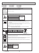
Parts name Check points
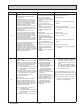
Disconnect the connector then measure the resistance with a tester.
(At the ambient temperature of 50 to 86˚F [10 to 30˚C])
Measure the resistance between the terminals with a tester.
Drain pump (DP)
Drain float switch (FS)
Refer to “9-6-1. Thermistor”.
Room temperature
thermistor (TH1)
Pipe temperature
thermistor/liquid(TH2)
Condenser/Evaporator
temperature thermistor
(TH5)
State of moving part
Abnormal
DOWN Other than open
UP
Normal
Open
Short Other than short
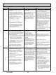
Measure the resistance between the terminals with a tester.
(At the ambient temperature of 68 to 86˚F [20 to 30˚C])
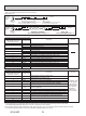
Vane motor (MV)
Vane motor for
i-See sensor (Option)
Red - Yellow (5–3, 0–8, 5–3, )–8)
Red - Blue (5–1, 0–6, 5–1, )–6)
Red - Orange (5–4, 0–9, 5–4, )–9)
Red - White (5–2, 0–7, 5–2, )–7)
Connector
Normal
300 " ± 7%
Measure the resistance between the terminals with a tester.
(At the ambient temperature of 68 to 86˚F [20 to 30˚C])
Red - Yellow
Red - Blue
Red - Orange
Red - White
Connector
Normal
250 " ± 7%
(Option)
2
1
Moving part
4
3
Switch
Magnet
Moving part
Yellow
Blue
Red
Orange
White
Yellow
Blue
Red
Orange
White
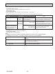
i-See sensor
1 2 3
4
1 2 3
4
Black
Black
Black
Black
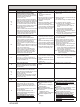
Turn the power ON while the i-See sensor connector is connected to the CN4Z on indoor
controller board. A communication between the indoor controller board and i-See sensor
board is made to detect the connection.
Normal: When the operation starts, the motor for i-See sensor is driven to rotate the i-See sensor.
Abnormal: The motor for i-See sensor is not driven when the operation starts.
Note: The voltage between the terminals cannot be measured accurately since it is pulse output.
1
2
3
Red
Purple
Black
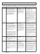
1 Check if the drain float switch works properly.
2 Check if the drain pump works and drains water properly in cooling operation.
3 If no water drains, confirm that the check code P5 will not be displayed 10 minutes after the
operation starts.
Note: The drain pump for this model is driven by the internal DC motor of controller board, so it is not
possible to measure the resistance between the terminals.
Normal
Red–Black: Input 13 V DC → The motor starts to rotate.
Purple–Black: Abnormal (check code P5) if it outputs 0–13 V square wave (5 pulses/rotation),
and the number of rotation is not normal.