
Indoor Installation Manual

3
2. Installation location
Refer to the outdoor unit installation manual.
3. Installingtheindoorunit
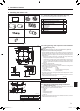
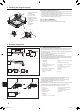
3.1.Checktheindoorunitaccessories(Fig.3-1)
The indoor unit should be supplied with the following accessories.
Accessory name Q'ty
1
Installation template (top of the package) 1
2
Washers (with insulation)
Washers (without insulation)
4
4
3
Pipe cover (for refrigerant piping joint)
Small diameter
Large diameter
1
1
4
Band (large) 6
5
Band (small) 2
6
Drain socket 1
7
Insulation 1
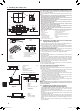
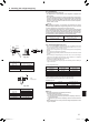
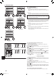
3.2.Ceilingopeningsandsuspensionboltinstallation
locations(Fig.3-2)
Caution:
Installtheindoorunitatleast2.4m,94-1/2inchaboveoororgradelevel.
For appliances not accessible to the general public.
• Usingtheinstallationtemplate(topofthepackage)andthegauge(suppliedasan
accessory with the grille), make an opening in the ceiling so that the main unit can
be installed as shown in the diagram. (The method for using the template and the
gauge is shown.)
* Before using, check the dimensions of template and gauge, because they
changeduetouctuationsoftemperatureandhumidity.
* The dimensions of ceiling opening can be regulated within the range shown in
Fig. 3-2; so center the main unit against the opening of ceiling, ensuring that the
respective opposite sides on all sides of the clearance between them becomes
identical.
• UseM10(3/8")suspensionbolts.
* Suspensionboltsaretobeprocuredattheeld.
• Installsecurely,ensuringthatthereisnoclearancebetweentheceilingpanel&
grille,andbetweenthemainunit&grille.
A Outer side of main unit E Grille
B Bolt pitch F Ceiling
C Ceiling opening G Multi functional casement (option)
D Outer side of Grille H Entire periphery
* Note that the space between ceiling panel of the unit and ceiling slab, etc. must be
7 mm, 5/16inchor more.
*Whentheoptionalmulti-functionalcasementisinstalled,add135mm,5-5/16inch
tothedimensionsmarkedonthegure.
(mm, inch)
Models A B
A12, A18 241,9-1/2" 258,10-3/16"
A24, A30, A36, A42 281,11-1/16" 298,11-3/4"
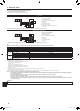
3.3.Refrigerantanddrainagepipinglocationsof
indoorunit(Fig.3-3)
Theguremarkedwith*inthedrawingrepresentthedimensionsofthemainunit
excluding those of the optional multi function casement.
A Drain pipe
B Ceiling
C Grille
D Refrigerant pipe (liquid)
E Refrigerant pipe (gas)
F Main unit
* Whentheoptionalmulti-functionalcasementisinstalled,add135mm,5-5/16inch
tothedimensionsmarkedonthegure.
(mm, inch)
Models C D
A12, A18 76,3" 76.5,3-1/82"
A24, A30, A36, A42 79.5,3-1/8" 79.5,3-1/8"
Fig.3-3
Fig.3-2
1 2
3 4
5 6
7
Fig.3-1
31-1/4
B
37-3/8
D
25-15/16
B
(
3/4
)
(
3/4
)
33-1/16
A
37
-
3/8 D
5-1/4
5-11/16
5-11/16
3-1/8
8-11/16
7-9/16
5-11/16
5-11/16
F
E
G
5-5/16
11/16
+
3/16
0
* B
A
F
E
1-9/16
+3/16
0
11/16
*4-1/8
*5-1/2
*6-11/16
*7-1/2
1/4
D
C
2-3/8 10-11/16
D
E
F
B
A
C
14-1/16
3-1/8
Min. 59 H
Floor
Min.94-1/2
3/4to1-3/4
33-7/8to35-13/16C
3/4to1-3/4
*2 to
2-3/4
33-7/8to35-13/16C
3/4to1-3/4
3/4to1-3/4
(inch)
(inch)
BH79D659K02.indb 3 2017/05/22 17:25:27