
Indoor Installation Manual


13
7. Test run
Step4 Conrmtheoperationoftheoutdoorunitfan.
The speed of the outdoor unit fan is controlled in order to control the performance of the unit. Depending on the ambient air, the fan will rotate at a slow speed and will keep
rotatingatthatspeedunlesstheperformanceisinsufcient.Therefore,theoutdoorwindmaycausethefantostoprotatingortorotateintheoppositedirection,butthisis
not a problem.
Step5 Stopthetestrun.
1Pressthe[ON/OFF]buttontostopthetestrun.(TheTestrunmenuwillappear.)
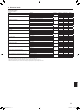
Note: If an error is displayed on the remote controller, see the table below.
LCD Description of malfunction LCD Description of malfunction LCD Description of malfunction
P1 Intake sensor error P9 Pipe sensor error (dual-wall pipe)
E0 – E5
Communication error between the
remote controller and the indoor
unit
P2 Pipe sensor error (liquid pipe) PA Leakage error (refrigerant system)
P4
Drainoatswitchconnector
disconnected (CN4F)
PB (Pb) Indoor unit fan motor error
PL Refrigerant circuit abnormal
P5 Drainoverowprotectionoperation FB Indoor controller board error
E6 – EF
Communication error between the
indoor unit and the outdoor unit
P6
Freezing/overheatingprotection
operation
U*,F*
(* indicates an
alphanumeric
character
excluding FB.)
Outdoor unit malfunction
Refer to the wiring diagram for the
outdoor unit.
P8 Pipe temperature error
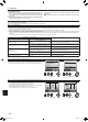
See the table below for the details of the LED display (LED 1, 2, and 3) on the indoor controller board.
LED1 (microcomputer power supply) Indicates whether control power is supplied. Make sure that this LED is always lit.
LED2 (remote controller power supply)
Indicates whether power is supplied to the wired remote controller. The LED is lit only for the indoor unit that is connected
to the outdoor unit that has an address of 0.
LED3(indoor/outdoorunitcommunication) Indicates whether the indoor and outdoor units are communicating. Make sure that this LED is always blinking.
Note:
If the unit is operated continuously during a test run, the unit stops after 2 hours.
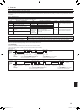
7.3.Self-check
■ Refertotheinstallationmanualthatcomeswitheachremotecontrollerfordetails.
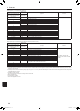
OPERATION
INDICATOR
lamp blinking
pattern
Beep Beep Beep Beep Beep Beep Beep
Off
Approx. 2.5 sec.
On
Approx. 3 sec.
On
0.5 sec.
On
0.5 sec.
On
0.5 sec.
On
0.5 sec.
Off
Approx. 2.5 sec.
On
Approx. 3 sec.
On
0.5 sec.
On
0.5 sec.
· · · Repeated
Numberofblinks/beepsinpatternindicatesthecheck
codeinthefollowingtable(i.e.,n=5for“U2”)
Numberofblinks/beepsinpatternindicates
the check code in the following table
n
th
1
st
2
nd
3
rd
1
st
2
nd
Self-check
starts
(Start signal
received)
Beeper sounds
[Output pattern B]
OPERATION
INDICATOR
lamp blinking
pattern
Beep
Beep Beep Beep Beep Beep Beep
Off
Approx. 2.5 sec.
On
0.5 sec.
On
0.5 sec.
On
0.5 sec.
On
0.5 sec.
Off
Approx. 2.5 sec.
On
0.5 sec.
On
0.5 sec.
· · · Repeated
Numberofblinks/beepsinpatternindicatesthecheck
code in the following table (i.e., n=5 for “P5”)
Numberofblinks/beepsinpatternindicates
the check code in the following table
n
th
1
st
2
nd
3
rd
1
st
2
nd
Self-check
starts
(Start signal
received)
Beeper sounds
• Refertothefollowingtablesfordetailsonthecheckcodes.(Wirelessremotecontroller)
[Output pattern A]
BH79D659K02.indb 13 2017/05/22 17:25:30