
Service manual


21
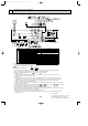
Unit : inch
Remote controller
FILTER
CHECK MODE
TEST RUN
TIMER OFF TIMER
CHECK SET TEMP.
CLOCK AUTO AUTO
START STOP
SWING
FAN
SPEED
5-1/8
4-3/4
3/4
3/32
23/32
AUTO
RETURN
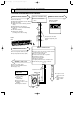
Pipe temperature
thermistor / Liquid
(RT2)
Distributor
Restrictor
valve
Capillary tube
PKH18FK3 : ({0.126x{0.071x19.7)
Refrigerant pipe
(option)
{3/8"
(with heat insulator)
Refrigerant pipe
(option)
{5/8"
(with heat insulator)
Strainer
Flared connection
Flared connection
PKH24FK3 : ({0.157x{0.079x19.7)w
w An error in this diagram has been
modified. The size of capillary tube
{0.157x{0.071x19.7, was wrong.
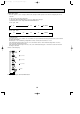
Distributor
Restrictor
valve
Capillary tube
Refrigerant pipe
(option)
{3/8"
(with heat insulator)
Refrigerant pipe
(option)
{5/8"
(with heat insulator)
Strainer
Flared connection
Flared connection
Pipe temperature
thermistor / Liquid
(RT2)
PKH30FK3 : ({0.157x{0.079x23.6)
PKH36FK3 : ({0.157x{0.079x15.7)
Distributor
Restrictor
valve
Capillary tube
Refrigerant pipe
(option)
{1/2"
(with heat insulator)
Refrigerant pipe
(option)
{3/4"
(with heat insulator)
Strainer
Flared connection
Flared connection
Pipe temperature
thermistor / Liquid
(RT2)
PKH18FK3
PKH24FK3
PKH30FK3
PKH36FK3
7
REFRIGERANT SYSTEM DIAGRAM
COOLING
HEATING
Refrigerant flow
OC273-A-1.qxp 03.11.25 8:59 AM Page 21