
Service manual


[ VIII Troubleshooting ]
- 25 -
HWE08010 GB
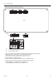
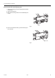
4. Voltage test points on the control board
1. PEFY-P06,08,12,15,18,24NMSU-E
Fuse Fuse(AC 250V 6.3A)
CND Power supply voltage (208 -
230VAC)
CN2M For M-NET transmission cable
connection (24 - 30VDC)
SWE Emergency operation
SW2 Capacity setting
SW4 Function setting
CN42 For address board connection
SW3 Function setting
CN81 For address board connection
CN32 Remote start/stop adapter
CN3A For MA remote controller cable
connection
(10 - 13 VDC (Between 1 and 3.))
CN4Y For fan control
CN52 Remote display
CN51 Centralized control
CN41 JAMA standard HA terminal A
CN44 Thermistor (liquid/gas tempera-
ture)
CN4F Float thermistor
CN24 For heater control
CN20 Thermistor (Inlet temperature)
CN3C Indoor-outdoor transmission
(0 - 24VDC)
CNMF Fan motor output
1 - 4: 310 - 340 VDC
5 - 4: 15 VDC
6 - 4: 0 - 6.5 VDC
7 - 4: Stop 0 or 15 VDC
Run 7.5 VDC
(0 - 15 pulse)
CNP Drain-up mechanism output
(200VAC)
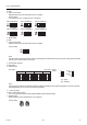
(*1)
V
FG
Voltage on the (-) side of PC941
and C25
(Same with the voltage between 7
(+) and 4 (-) of CNMF)
V
CC
Voltage between the C25 pins
15 VDC
(Same with the voltage between 5
(+) and 4 (-) of CNMF)
Vsp Voltage between the C951 pins
0VDC (with the fan stopped)
1 - 6.5VDC (with the fan in opera-
tion)
(Same with the voltage between 6
(+) and 4 (-) of CNMF)
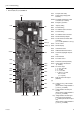
Fuse
CND
С25(*1)
CN2M
SWE
SW2
SW4
CN42
SW3
CN81
CN32
LED2 CN3A CN60 CN4Y
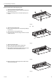
CN52
CN51
CN41
CN44
CN4F
CN20
CN24
CN3C
LED1
PC941(*1)
C951(*1)
CNMF
CNP