
Service manual

[ VI Refrigerant System Diagram ]
- 9 -
HWE08010 GB
VI Refrigerant System Diagram
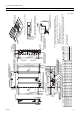
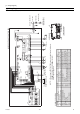
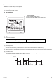
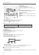
[1] Refrigerant system diagram
(A) Gas pipe thermistor TH23
(B) Gas pipe
(C) Liquid pipe
(D) Brazed connections
(E) Strainer (#100 mesh)
(F) Linear expansion valve
(G) Liquid pipe thermistor TH22
(H) Heat exchanger
(I) Room temperature thermistor TH21
(H)
(I)
(F)
(E)(E)
(C)
(G)
(A)
(D)
(B)
mm[in.]
Capacity PEFY-P06,08,12,15NMSU-E PEFY-P18NMSU-E PEFY-P24NMSU-E
Gas pipe ø12.7 [1/2] R410A: ø12.7 [1/2]
R22: ø15.88 [5/8]
ø15.88 [5/8]
Liquid pipe ø6.35 [1/4] R410A: ø6.35 [1/4]
R22: ø9.52 [3/8]
ø9.52 [3/8]