Air-Conditioners PEAD-RP71, 100, 125, 140JAA INSTALLATION MANUAL FOR INSTALLER For safe and correct use, please read this installation manual thoroughly before installing the air-conditioner unit.
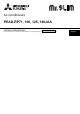
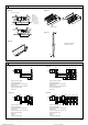
3 3.1 [Fig. 3-1] 50~150 C B A C A 57 643 B 450 4 450 23 D 98 30 D 2 1 B A B C D E F G 250 3 F Access door 1 600 mm or more Electrical parts box 2 100 mm or more Air inlet 3 10 mm or more Air outlet 4 300 mm or more Ceiling surface Service space (viewed from the side) Service space (viewed from the direction of arrow) E A (mm) E 777 G Model PEAD-RP71 PEAD-RP100, 125 PEAD-RP140 4 A B C D E 1100 1154 1200 1060 1200 1400 1454 1500 1360 1500 1600 1654 1700 1560 1700 4.1 [Fig.
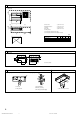
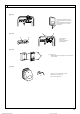
6 6.1 [Fig. 6-1] øB a øA Model PEAD-RP71, 100, 125, 140 b A ø15.88 B ø9.52 a Indoor unit b Outdoor unit 6.2 [Fig. 6-3] [Fig. 6-4] b a [Fig. 6-5] c d 90° e b a f a c b d a Copper tubes b Good c No good d Tilted a Burr b Copper tube/pipe e Uneven f Burred [Fig. 6-6] c Spare reamer d Pipe cutter a Flare nut b Copper tube 6.3 [Fig. 6-7] a a A b e e f g h b d b c [Fig.
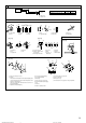
6 6.5 [Fig. 6-10] [Fig. 6-11] A A B F E 1 C C C 5 25 C D G B E D A B C D E 4 Downward slope 1/100 or more Connection dia. R1 external thread Indoor unit Collective piping Maximize this length to approx. 10 cm 2 A B C D E F G Indoor unit Tie band (accessory) Band fixing part Insertion margin Drain socket (accessory) Drain pipe (O.D.
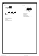
7 7.1 [Fig. 7-1] [Fig. 7-2] In case of rear inlet A Duct B Air inlet C Access door D Canvas duct E Ceiling surface F Air outlet G Leave distance D A A C E F B A enough to prevent short cycle G B In case of bottom inlet D A A C [Fig. 7-4] E C A Filter B Bottom plate F B G [Fig. 7-3] C Nail for the bottom inlet D Nail for the rear inlet D 8 8.1 [Fig. 8-1] [Fig.
8 8.2 [Fig. 8-2-1] [Fig. 8-2-2] D B A Screw holding cover (1pc) B Cover A C E [Fig. 8-2-3] C Terminal box D Knockout hole E Remove [Fig. 8-2-4] J K G F I H F Use PG bushing to keep the weight of the cable and external force from being applied to the power supply terminal connector. Use a cable tie to secure the cable.
8 8.2 [Fig. 8-3] A Indoor terminal block 2 1 2 A Indoor terminal block B Earth wire (green/yellow) C Indoor/outdoor unit connecting wire 3core 1.5 mm2 or more D Outdoor terminal block E Power supply cord : 2.0 mm2 or more 1 Connecting cable Cable 3-core 1.5 mm2, in conformity with Design 245 IEC 57. 2 Indoor terminal block 3 Outdoor terminal block B Earth wire (green/yellow) 4 5 1 C Indoor/outdoor unit connecting wire 3-core 1.
8.4 [Fig. 8-7] Standard 1:1 A Indoor/outdoor wiring OC(00) Signal receiving unit wiring B TB1 A B C D TB4 IC CN90 C 1 Outdoor unit Refrigerant address Indoor unit Signal receiving unit D [Fig. 8-8] A F B A B C D E F G H E G C D Signal receiving unit external Center of Switch box Switch box Installation pitch 6.5 mm (1/4 inch) 70 mm (2 - 3/4 inch) 83.5 ± 0.4 mm (3 - 9/32 inch) Protrusion (pillar, etc) H [Fig.
8 8.4 [Fig. 8-12] Insert the minus screwdriver toward the arrow pointed and wrench it to remove the cover. A flat screwdriver whose width of blade is between 4 and 7mm (5/32 - 9/32inch) must be used. C [Fig. 8-13] A B D A B C D Thin-wall portion Bottom case Remote controller wire Conducting wire [Fig. 8-14] A A Screw (M4 x 30) * When installing the lower case directly on the wall or the ceiling, use wood screws. [Fig. 8-15] 1 1 A 1 Hang the cover to the upper hooks (2 places).
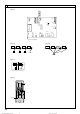
8 8.4 [Fig. 8-16] JP1 JP2 JP3 JP41 JP42 CN32 SW1 CN3C CN105 CN41 SW2 CN2A OFF CN51 SWE ON CN22 CN90 CNXB2 CN4F CN44 CN20 CN2L CNXA2 CNXC2 A [Fig. 8-17] [Fig. 8-18] IC IC CN90 IC CN90 Pair number: 0 Pair number: 0 IC CN90 Pair number: 1 CN90 Pair number: 2 Pair number: 1 Pair number: 3 Pair number: 2 IC CN90 Pair number: 0 IC CN90 Pair number: 0 Pair number: 3 Pair number: 0 [Fig.
8 8.5 [Fig. 8-21] 2 3 4 4 1 TEMP. F E G MENU BACK PAR-21MAA MONITOR/SET ON/OFF ON/OFF 1 A FILTER DAY CLOCK 2 CHECK TEST OPERATION B CLEAR 1 C D [Fig.
10 10.1 B [Fig.
Contents 1. 2. 3. 4. 5. Safety precautions ................................................................................. Selecting the installation location ........................................................... Selecting an installation site & Accessories ........................................... Fixing hanging bolts ............................................................................... Installing the unit ................................................................................
3. Selecting an installation site & Accessories • Select a site with sturdy fixed surface sufficiently durable against the weight of unit. • Before installing unit, the routing to carry in unit to the installation site should be determined. • Select a site where the unit is not affected by entering air. • Select a site where the flow of supply and return air is not blocked. • Select a site where refrigerant piping can easily be led to the outside.
6. Refrigerant piping work 6.1. Refrigerant pipe [Fig. 6-5] (P.3) a Flare nut b Copper tube [Fig. 6-1] (P.3) a Indoor unit b Outdoor unit Refer to the Instruction Manual that came with the outdoor unit for the restrictions on the height difference between units and for the amount of additional refrigerant charge. • Remove flare nuts attached to indoor and outdoor unit, then put them on pipe/tube having completed burr removal. (not possible to put them on after flaring work) 6.2.4. Flaring work [Fig.
6. Refrigerant piping work 1.Remove and discard the rubber bung which is inserted in the end of the unit piping. Tighten the cap to the service port to obtain the initial status. 2.Flare the end of the site refrigerant piping. 3.Pull out the thermal insulation on the site refrigerant piping and replace the insulation in its original position.
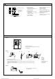
7. Duct work • • • • Connect canvas duct between unit and duct. [Fig. 7-1] (P.5) Use incombustible material for duct parts. Provide full insulation to inlet duct flange and outlet duct to prevent condensation. Be sure to change the position of air filter to a position where it can be serviced.
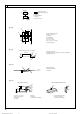
8. Electrical work 8.1. Power supply 8.1.1. Indoor unit power supplied from outdoor unit 8.1.2. Separate indoor unit/outdoor unit power supplies (For PUHZ application only) The following connection patterns are available. The outdoor unit power supply patterns vary on models. The following connection patterns are available. The outdoor unit power supply patterns vary on models. 1:1 System 1:1 System * The optional wiring replacement kit is required. [Fig. 8-1] (P.5) A B C D E F G [Fig. 8-3] (P.
8. Electrical work 8.2. Indoor wire connection [Fig. 8-5] (P.7) Work procedure 1.Remove 2 screws to detach the electric component cover. 2.Route each cable through the wiring intake into the electric component box. (Procure power cable and in-out connecting cable locally and use remote control cable supplied with the unit.) 3.Securely connect the power cable and the in-out connecting cable and the remote control cable to the terminal blocks. 4.
8. Electrical work 8.4.2. Signal Receiving Unit [Fig. 8-11] (P.8) 1) Sample system connection [Fig. 8-7] (P.8) Only the wiring from the signal receiving unit and between the remote controllers is shown in [Fig. 8-7]. The wiring differs depending on the unit to be connected or the system to be used. For details on restrictions, refer to the installation manual or the service handbook that came with the unit. 1. Connecting to Mr.
8. Electrical work 8.5. Function settings (Function selection via the remote controller) 2) For wireless remote controller [Fig. 8-22] (P.11) 1. Changing the external static pressure setting. 8.5.1 Function setting on the unit (Selecting the unit functions) • Be sure to change the external static pressure setting depending on the duct and the grill used. 1) For wired remote controller [Fig. 8-21] (P.11) 1. Changing the external static pressure setting.
9. Test run 9.1. Before test run 9.2. Test run After completing installation and the wiring and piping of the indoor and outdoor units, check for refrigerant leakage, looseness in the power supply or control wiring, wrong polarity, and no disconnection of one phase in the supply. Use a 500-volt megohmmeter to check that the resistance between the power Ω. supply terminals and ground is at least 1.0 MΩ Do not carry out this test on the control wiring (low voltage circuit) terminals. Warning: Ω.
9. Test run 9.3. Test run 9.3.1. Using wireless remote controller (option) [Fig. 9-3] (P.11) 1 Turn on the power to the unit at least 12 hours before the test run. 2 Press the TEST RUN button A twice continuously. (Start this operation from the status of remote controller display turned off.) TEST RUN and current operation mode are displayed. 3 Press the MODE button B to activate COOL mode, then check whether cool air is blown out from the unit.
9. Test run On the wireless remote controller with conditions above, following phenomena takes place. • No signals from the remote controller are accepted. • OPE lamp is blinking. • The buzzer makes a short ping sound. Note: Operation is not possible for about 30 seconds after cancellation of function selection. (Correct operation) For description of each LED (LED1, 2, 3) provided on the indoor controller, refer to the following table.
Please be sure to put the contact address/telephone number on this manual before handing it to the customer. HEAD OFFICE: TOKYO BLDG.