Air-Conditioners INDOOR UNIT GB PEA-RP170,200 WHA INSTALLATION MANUAL For safe and correct use, please read this installation manual thoroughly before installing the air-conditioner unit.
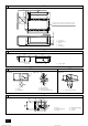
3 3.2 [Fig. 3.2.1] 800 1100 200~300 150~200 C B 1350 1034 450 A 1100 37 23 more than 20 1250 1324 23 E 30 ±10 470 more than 100 more than 20 D 50 60 50 730 Keep the service space for the maintenance from the bottom when the heat exchanger is cleaned. A 4 A Access door B Electrical parts box C Air inlet D Air outlet E Ceiling surface A Center of gravity 4.1 [Fig. 4.1.1] 1324 235 1034 494 701 A 5 5.1 [Fig. 5.1.1] 5.3 C [Fig. 5.1.2] [Fig. 5.3.
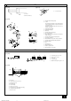
7 7.1 [Fig. 7.1.1] [Fig. 7.1.2] A A A Cut here B Remove brazed cap Cool by a wet cloth [Fig. 7.1.3] A A Thermal insulation tubing (small) B Caution: Pull out the thermal insulation on the refrigerant piping at the site, braze the piping, and replace the insulation in its original position. B C Take care to ensure that condensation does not form on exposed copper piping.
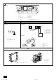
8 [Fig. 8.0.1] D D C C B I A 9 E H F G A Air inlet B Air filter (supplied at site) C Duct D Canvas duct E Access door F Ceiling G Ensure sufficient length to prevent short cycling H Air outlet I Keep duct-work length 850 mm or more 9.1 9.2 [Fig. 9.1.1] [Fig. 9.2.1] B A S1 S2 S3 S1 S2 S3 1 2 TB4 A TB15 B A Terminal block for indoor transmission cable B Terminal block for outdoor transmission cable C Remote controller C [Fig. 9.2.
[Fig. 9.3.3] E I L F N L N G K 1 M J S1 S2 S3 L 2 H S1 S2 S3 O N E Use PG bushing to keep the weight of the cable and external force from being applied to the power supply terminal connector. Use a cable tie to secure the cable. Wind the wire around the cable strap once to keep it from being pulled out.
GB Contents 1. Safety precautions ...................................................................................... 1.1. Before installation and electric work .......................................... 1.2. Precautions for devices that use R410A refrigerant .................. 1.3. Before getting installed .............................................................. 1.4. Before getting installed (moved) - electrical work ...................... 1.5. Before starting the test run .......................
1.3. Before getting installed • • • Caution: • • • • • • Do not install the unit where combustible gas may leak. - If the gas leaks and accumulates around the unit, an explosion may result. Do not use the air conditioner where food, pets, plants, precision instruments, or artwork are kept. - The quality of the food, etc. may deteriorate. Do not use the air conditioner in special environments. - Oil, steam, sulfuric smoke, etc.
• At a distance 1 m or more away from your TV and radio (to prevent picture from being distorted or noise from being generated). 3.2. Securing installation and service space • In a place as far away as possible from fluorescent and incandescent lights (so the infrared remote control can operate the air conditioner normally). • Select the optimum direction of supply airflow according to the configuration of the room and the installation position.
6.1. Refrigerant pipe and drain pipe specifications Model 170·200 Item Refrigerant pipe (Brazing connection) Liquid pipe Gas pipe ø 9.52 ø 25.4 O.D. ø 32 Drain pipe 6.2. Refrigerant pipe, drain pipe [Fig. 6.2.1] (P.2) Air outlet 7.1. Refrigerant piping work Caution: • Caution: • Install the refrigerant piping for the indoor unit in accordance with the following. 1. Cut the tip of the indoor unit piping, remove the gas, and then remove the brazed cap. • [Fig. 7.1.1] (P.
8. Duct work • When connecting ducts, insert a canvas duct between the main body and the duct. A Air inlet B Air filter (supplied at site) • Use non-combustible duct components. C Duct D Canvas duct • Install sufficient thermal insulation to prevent condensation forming on outlet duct flanges and outlet ducts. E Access door F Ceiling G Ensure sufficient length to prevent short cycling H Air outlet [Fig. 8.0.1] (P.
Caution: Install wiring so that it is not tight and under tension. Wiring under tension may break, or overheat and burn. 9.4. Function settings (Function selection via the remote controller) 9.3. Connecting electrical connections 9.4.1 Please identify the model name of the operation manual attached on the terminal bed box cover with that shown on the rating name plate. 1. Remove the screw (2pcs) holding the cover to dismount the cover. B Cover 2.
9.5. Before test run 9.6. Test run s After completing installation and the wiring and piping of the indoor and outdoor units, check for refrigerant leakage, looseness in the power supply or control wiring, wrong polarity, and no disconnection of one phase in the supply. s Use a 500-volt megohmmeter to check that the resistance between the Ω. power supply terminals and ground is at least 1.0 MΩ s Do not carry out this test on the control wiring (low voltage circuit) terminals. 9.6.1.
This product is designed and intended for use in the residential, commercial and light-industrial environment. The product at hand is based on the following EU regulations: • • Low Voltage Directive 2006/95/EC Electromagnetic Compatibility Directive 2004/108/EC Please be sure to put the contact address/telephone number on this manual before handing it to the customer. HEAD OFFICE: TOKYO BLDG.