
Specifications


90
•When controlling each unit (unit 01 to 04) individually ➜
Select "01" to "04."
•When controlling all the units (unit 01 to 04) at once ➜
Select "AL" (all).
Wireless remote controller type
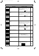
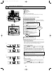
Flow of function selection procedure
The flow of the function selection procedure is shown below. This example shows how to turn
off the function that raises the set temperature by 4 degrees during HEAT operation. The
procedure is given after the flow chart.
1 Check the function selection setting.
2 Switch to function selection mode.
(Press the TIMER OFF button in
troubleshooting mode.)
Troubleshooting mode is the mode entered when you
set the adjustment switch on the back of the wireless
remote controller operation area to "ADJUST".
3 Specify unit No. "01" (since the function applies to unit 01).
(Set address "01" while still in troubleshooting mode, then press the HOUR button.)
Note: You can't specify the refrigerant address.
4
Select mode No. "24" (function that raises set temperature by 4 degrees during HEAT operation).
(Set address "24" while still in troubleshooting mode, then press the HOUR button.)
6
Finished
7 End function selection mode.
(End troubleshooting mode.)
YES
NO
Note: When you switch to function selection mode
on the wireless remote controller, the unit
ends function selection mode automatically if
nothing is input for 10 minutes or longer.
5 Select setting No. "02" (OFF).
(Set address "02" while still in troubleshooting mode, then press the HOUR button.)
ON/OFF
CHECK
ADDRESS
UNIT No.
FUNCTION No.
SELECTION No.
AM
PM
RESET
AM
PM
TEST RUN
FUNCTION
˚C
MODE FAN
VANE
TEMP.
START
STOP
HR.
MIN.
c
E
D
F
A
B
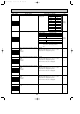
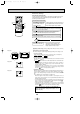
[Operating instructions] (entering settings with a wireless remote controller)
Changing the power voltage setting
Be sure to change the power voltage setting depending on the voltage used.
1 Go to the set mode
Set the Nrm/Set switch of the remote controller to Set. (see diagram 1)
, and will start to flash.
2 Go to the function select mode
Direct the wireless remote controller toward the sensor of the indoor unit and
press the button A.
➜ will become lit and “00” will start to flash in the unit number dis-
play (see diagram 2). When the signal from the remote controller is
received by the sensor, a single “beep” can be heard and the sensor-
operation indicator will flash.
* If the signal was not received by the sensor or an error occurred during
transmission, you will not hear a beep or a “double beep” may be heard.
Press the button E and repeat the procedure.
3 Setting the unit number
Make sure that “00” is flashing in the unit number display. Direct the wireless
remote controller toward the sensor of the indoor unit and press the
button B. (The display changes at each press: 00
➜ 01 ➜ 02 ➜ 03 ➜ 04 ➜
AL)
➜ “01” will flash in the mode display (see diagram 3).
When the signal from the remote controller is received by the sensor, a
single “beep” can be heard, the sensor-operation indicator will flash and
the draft operation will start.
* If a unit number that cannot be recognized by the unit is entered, three
beeps (3 deeps of 0.4 seconds duration) will be heard. Press the
button F and reenter the unit number setting.
* If the signal was not received by the sensor or an error occurred during
transmission, you will not hear a beep or a “double beep” may be heard.
Press the button F and reenter the unit number setting.
FUNCTION
TEST RUN
CHECK
STOP
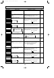
Unit number setting
00
FUNCTION
HR
START
START
Diagram 1
Diagram 2
0
1
Mode selection
Diagram 3
Nrm Set
OCT03-E-3.qxp 04.3.26 1:50 PM Page 90