
Specifications


79
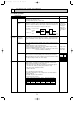
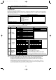
● Jumper connector function table
Switch
Signal
J1
J2
J3
J4
J5
J6
CN31
No.
Function Effective timing
Action by the switch operation
Switch of single phase and
3 phase power supply
Switch of cooling
only/cooling and heat pump
When power supply ON
When power supply ON
Single phase3 phase
When power supply ON
Cooling and heat pumpCooling only
Capacity switch
Emergency operation Emergency operation Normal When power supply ON
ON OFF
Model
Setting
J3 J4 J5 J6
:Short :Open
P1
P1.6
P2
P2.5
P3
P4
P5
P6
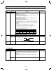
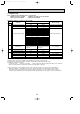
● Function of switches on M-NET board
Dip
Switch
1
2
3
4
0
1
2
3
4
5
6
7
8
9
No.
Function Effective timing
Action by the switch operation
Switching the display of
M-NET/Communications
among boards
AlwaysM-NET communication
Communication among boards
(serial communication)
No function
No function
No function
M-NET address No.
SW11(Unit's place)
SW12(Ten's place)
Under suspension
ON OFF
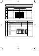
<Example of arrangement>
M-NET address No.
12
~
Arrangement
of switches
1
2
3
4
5
6
7
8
9
0
1
2
3
4
5
6
7
8
9
0
1
2
3
4
5
6
7
8
9
0
1
2
3
4
5
6
7
8
9
0
1
2
3
4
5
6
7
8
9
0
1
2
3
4
5
6
7
8
9
0
50
SW11
(Unit's place)
SW12
(Ten's place)
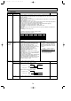
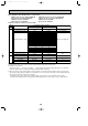
Switch
SW1
SW11
SW12
Rotary
Switch
Type of
Switch
—
—
—
—
—
—
—
—
—
OCT03-E-3.qxp 04.3.26 1:50 PM Page 79