
Specifications


77
DIP SWITCH FUNCTION
9
9-1. Indoor unit
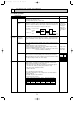
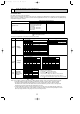
DIP switch and jumper connector functions.
Each function is controlled by the jumper connector in the controller board. Below table shows that the function setting by the
jumper connector is available or not in the controller board of applicable units. Also J11~15 (SW1) and J21~24 (SW2) has Dip
switch with their jumper connector.
Functions and signification of the jumper connector (Dip switch)
PKH–P·GALH / PKA-P·GAL
PKH–P·FALH / PKA-P·FAL
PCH–P·GAH / PCA-P·GA
PCA–P·HA
PLH–P·KAH / PLA-P·KA
PLH–P·AAH / PLA-P·AA
PMH–P·BA
PSH–P·GAH / PSA-P·GA
J11~J15 (SW1) ; Unit setting
J21~J24 (SW2) ; Capacity setting
Applicable units
;Changeable function
;Not changeable function
INDOOR CONTROLLER BOARD
type Btype A
J11~J15
(SW1)
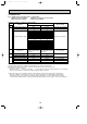
PKH–P2.5, 3, 4FALH / PKA–P2.5, 3, 4FAL
PCH–P2, 2.5, 3, 4, 5, 6GAH / PCA–P2, 2.5, 3, 4, 5, 6GA
PLA–P1.6, 2, 2.5KA
PLA–P3, 4, 5, 6KA
PLH–P3, 4, 5, 6KAH / PCA-P3, 5HA
PLH–P1.6, 2, 2.5KAH
PKH–P1.6, 2GALH / PKA–P1.6, 2GAL
PLA–P3, 4, 5, 6AA
PLH–P3, 4, 5, 6AAH
PMH–P1, 1.6, 2BA, BA1
PMH–P1, 1.6, 2BA2
Models
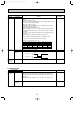
J11~J15 (SW1)
type AFunction
Model
settings
Capacity
settings
Pair number
setting with
wireless remote
controller
J11 J12 J13 J14 J15
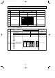
PSH–P·GAH / PSA–P·GA
Models
J11~J15 (SW1)
type B
J11 J12 J13 J14 J15
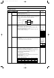
J21~J24
(SW2)
J41
J42
P1
P1.6
P2
P2.5
P3
P4
P5
P6
Models
J21~J24 (SW2)
In above table Jumper connector: Short, Open
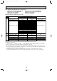
Note 1: If the settings of SW1 (model settings) or SW2 (capacity settings) on the service PCB are made incorrectly:
•If the SW1 settings are made incorrectly, the unit will not operate, or won't be able to operate normally.
•The SW1 (model) and SW2 (capacity) settings are used to send the indoor unit's model and capacity
information to the outdoor unit. The outdoor unit uses this information to perform control, so the expected
performance may not be achieved if the information is incorrect.
•In models with indoor fan phase control, pulsation control or DC fan control, the SW2 (capacity) settings are
used to control the fan air volume. If the settings are made incorrectly, the air volume may be higher or lower
than expected, performance may drop, or the noise level may increase.
J21 J22 J23 J24
0
1
2
3 ~ 9
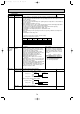
Wireless remote
controller setting
Control PCB setting
J41 J42
P1
P1.6
P2
P2.5
P3
P4
P5
P6
Models
SW2
1
ON
ON
ON
ON
ON
OFF
OFF
ON
2
OFF
ON
OFF
ON
OFF
OFF
ON
ON
3
OFF
OFF
ON
ON
OFF
ON
ON
ON
4
OFF
OFF
OFF
OFF
ON
ON
ON
ON
Service PCB
<Settings at time of factory shipment>
Wireless remote controller: 0
Control PCB: (for both J41 and J42)
Four pair number settings are supported.
The pair number settings of the wireless remote controller
and indoor control PCB (J41/J42) are given in the table on
the left. (' ' in the table indicates the jumper line is disconnected.)
OCT03-E-3.qxp 04.3.26 1:50 PM Page 77