
Specifications


57
MICROPROCESSOR CONTROL6
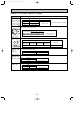
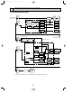
6-1. FUNCTIONAL BLOCK CHART
OUTDOOR UNIT SIDE
INDOOR UNIT SIDE
AC220, 230, 240V
AC380, 440, 415V
Power supply
terminal bed
Current
detection
Compressor
Fuse
Fuse
Connecting terminal
bed between the
indoor and outdoor unit
Connecting terminal
bed between the
indoor and outdoor unit
Remote controller
terminal bed
Remote controller
terminal bed
Communication
link
Communication
link
Communication
link
•Drain pump
•Louver
•Dew prevention heater
Relay
Relay
Relay
Relay
Driver
Driver
Fan control
Fan control
Driver
Microprocessor
Indoor fan
Vane
Vane
Outdoor fan
Crankcase
heater
LEV
DC/DC
converter
Fuse
DC5V
12V
5V
4A
DC14V
DC24V
AC220~240V
AC220~240V/DC24V
PL(H)(A)-P1.6~2.5KA(H)
only
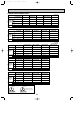
Indoor powerboard
Indoor controller
LED1
Power supply
for Microprocessor
LED2
Power supply
for Remote controller
Notes : As for PMH-P•BA, Indoor powerboard and Indoor controller on the whole.
LED3
Communication
between the indoor
and outdoor unit
DC/DC
converter
Current
detection
Key entry
Liquid crystal display
Transmission /
Receiving signal
DC5V for
Microprocessor
4-way valve,
Solenoid valve
Electromagnetic
contactor
OCT03-E-2.qxp 04.3.26 1:48 PM Page 57