
Specifications


44
33
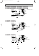
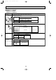
PCH-P2, P2.5, P3, P4, P5, P6GAH
PCA-P2, P2.5, P3, P4, P5, P6GA
1
1
2
2
3
3
Red
White
Black
Relay connector
1
2
Gray
Gray
4
5
2
361
Orange
Red
Pink
Yellow Brown Blue
M
4
2
5
31
Pink
Orange
Red
Yellow Blue
M
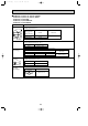
Parts name Check points
Measure the resistance between the terminals using a tester.
(Winding temperature 20:)
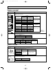
Measure the resistance between the terminals using a tester.
(Winding temperature 20:)
Drain-up
mechanism (Option)
Fan motor
Abnormal
Open or short
Normal
195"
107"
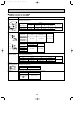
Measure the resistance between the terminals using a tester.
Contactor
(Only P2~P6GAH)
Abnormal
Open or short
10 11
88H
Normal
P2~P6
Abnormal
Open or short
Red–Black
White–Black
Motor terminal
or
Relay connector
P2
70.6"
69.6"
P2.5, P3
45.0"
44.8"
P4
43.7"
55.3"
P5, P6
20.4"
20.7"
Normal
Open or short
Abnormal
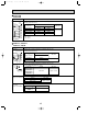
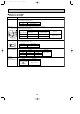
Brown–Yellow
Brown–Blue
Red–Orange
Red–Pink
Connector
P2
186~214"
P2.5, P3
140~160"
Normal
Open or short
Abnormal
Brown–Yellow
Brown–Blue
Red–Orange
Red–Pink
Connector
P4, P5, P6
140~160"
Normal
Vane motor
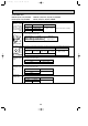
Measure the resistance of each heater element by using a tester.
(Surrounding temperature 20:)
Heater
(Only P2~P6GAH)
Normal
Abnormal
P2
13.7"
0.467kW 80V
P2.5, P3
9.1"
0.7kW 80V
P4
7.1"
0.9kW 80V
P5, P6
6.4"
1.0kW 80V
Open or short
Protector
OFF:130i5:
ON :80i20:
OCT03-E-2.qxp 04.3.26 1:48 PM Page 44