
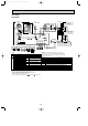
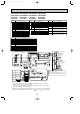
Specifications
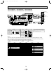

15
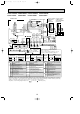
NAME
SYMBOL
NAME
SYMBOL SYMBOL
NAME
CN2
R.B
HEATER
HEATER THERMAL SWITCH
THERMAL FUSE (110°C 16A)
HEATER
26H
FS1,2
HEATER CONTACTOR88H
H
CONNECTOR(PROGRAM TIMER)
REMOTE CONTROLLER BOARD
TRANSMISSON LINE)
TERMINAL BLOCK(REMOTE CONTROLLER
TB6
RELAY(FAN MOTOR)X6
X5
X4
X2
SWE
SW2
SW1
JUMPER WIRE(MODEL SELECTION)
JUMPER WIRE(CAPACITY CORD)
SWITCH(EMERGENCY OPERATION)
RELAY(LOUVER)
RELAY(FAN MOTOR)
RELAY(FAN MOTOR)
LED3
LED2
POWER SUPPLY(R.B)
TRANSMISSOION(INDOOR • OUTDOOR)
I.B
CN2L
CN41
CN32
LED1
INDOOR CONTROLLER BOARD
CONNECTOR(LOSSNAY)
CONNECTOR(HA TERMINAL-A)
CONNECTOR(REMOTE SWITCH)
POWER SUPPLY(I.B)
FUSE(4A)
INDOOR POWER BOARD
VARISTOR
P.B
F1
ZNR
CAPACITOR(FAN MOTOR)
FAN MOTOR
LOUVER MOTOR
TERMINAL BLOCK(HEATER)
TB2
ML
MF
TB4
(INDOOR/OUTDOOR CONNECTING LINE)
TERMINAL BLOCK
ROOM TEMPERATURE THERMISTOR
(0°C/15k",25°C/5.4k" DETECT)
COND./EVA. TEMPERATURE THERMISTOR
PIPE TEMPERATURE THERMISTOR/LIQUID
(0°C/15k",25°C/5.4k" DETECT)
(0°C/15k",25°C/5.4k" DETECT)
TH1
TH2
TH5
C
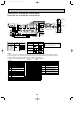
NOTES:
1.Since the outdoor side electric wiring may change be sure to check the
outdoor unit electric wiring for servicing.
2.Indoor and outdoor connecting wires are made with polarities,make wiring
matching terminal numbers(S1,S2,S3).
3.Make sure that the main power supply of the booster heater is independent.
4.Symbols used in wiring diagram above are, :Connector, :Terminal (block).
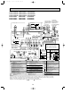
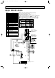
J21 J22 J23 J24
J21 J22 J23 J24
J21 J22 J23 J24
J24J23J22
OFF
ON
4321
Manufacture
<For manufacture>
SW1
SW2
MODELS
J14J13J12J11 J15
Service board
OFF
ON
4321
OFF
ON
4321
J21
OFF
ON
4321
3GA(H)
4GA(H)
5GA(H)
6GA(H)
123 5
ON
OFF
4
<For service board>
Abnormality of the signal transmission between remote controller
and indoor unit.
( “EE” indicates abnormality of combination).
Abnormality of the signal transmission between indoor unit outdoor unit
E6 EF
E0 E5
Abnormality of pipe temperture thermistor/liquid(TH2).
Abnormality of room temperture thermistor(TH1).
Symptom
Abnormality of pipe temperature thermistor/Cond./Eva.(TH5).
Abnormality of pipe temperature.
Freezing/overheating protection is working.
P2
P1
Check code
P6
P8
P9
Abnormality in outdoor unit.Refer to outdoor unit wiring diagram.
U0 UL
F F F F
No corresponding unit.
No trouble generated in the past.
Abnormality in outdoor unit.Refer to outdoor unit wiring diagram.
- - - -
F1 F9
Please set the voltage using the
remote controller.
For the setting method,please refer to
the indoor unit installation Manual.
PE
PE
TB1
TB1
CN24
1
BLU
2
3
2
1
CN31
2
1
2
1
1
2
1
2
J24
J23
J22
P.B
ZNR
X4X5
LOUVER
CNL
(YLW)
13
X6 X5
X6
1357
RED
C
ORN
MF
FAN
(WHT)
LED3 LED2 LED1
R.B
INDOOR UNIT
TRANSMISSION WIRE
DC14V
J21
OFF
ON
SWE
SW2
WIRELESS
INTAKE
CN20
(RED)
LIQUID
CN21
(WHT)
REMOCON
CN22
(BLU)
CN90
(WHT)
POWER
CN2D
(WHT)
POWER
CN03
(RED)
S3
S2
S1
N
L
F1
OUTDOOR
CN01(BLU)
3
2
1
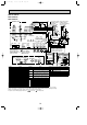
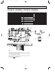
<PU(H)-P3/P4VGAA.UK>
<PU(H)-P3VGA>
POWER SUPPLY
(1PHASE)
220-240V 50Hz
OUTDOOR UNIT
S1
S3
S2
CONT.BOARD
CN02(WHT)
CN2S(WHT)
DC14V
1
2
3
2
1
TH1
CN2
TB6
I.B
TH2
ML
513
CN41
CN2L
CN32
X4
X2
X2
BLK
BLU
YLW
WHT
YLW
YLW
YLW
ORN
BRN
WHT
BLK
YLW
ORN
BRN
SW1
J11
J12
J13
J14
J15
L3
L2
L1
S1
S3
S2
TB4
N
<PU(H)-P3YGA 6YGA>
<PU(H)-P3YGA~6YGAA.UK>
POWER SUPPLY
3N-(3PHASE 4WIRES)
380-415V 50Hz
TH5
1
2
PIPE
CN29
(BLK)
BLU
PE
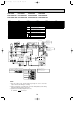
<Only models PSH-P · GAH>
WHT
RED RED
YLW
RED
RED
88H
2
1
I.B
26H
6
5
6
1
HEATER
CN24
(YLW)
FS1FS2
BLU
BRN
5
2
1
3
88H
H
TB2
N
L
YLW
YLW
POWER SUPPLY
(1PHASE)
220-240V 50Hz
PSH-P3GAH PSH-P4GAH PSH-P5GAH PSH-P6GAH
PSH-P3GAH1 PSH-P4GAH1 PSH-P5GAH1 PSH-P6GAH1
PSA-P3GA PSA-P4GA PSA-P5GA PSA-P6GA
PSA-P3GA1 PSA-P4GA1 PSA-P5GA1 PSA-P6GA1
OCT03-E-1.qxp 04.3.26 1:38 PM Page 15