
Specifications


132
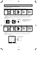
● PUH-P1VGAA PUH-P1.6VGAA PUH-P2VGAA PUH-P2.5VGAA PUH-P3VGAA PUH-P4VGAA
PUH-P1.6YGAA PUH-P2YGAA PUH-P2.5YGAA PUH-P3YGAA PUH-P4YGAA
PUH-P5YGAA PUH-P6YGAA
PU-P1.6VGAA PU-P2VGAA PU-P2.5VGAA PU-P3VGAA PU-P4VGAA
PU-P1.6YGAA PU-P2YGAA PU-P2.5YGAA PU-P3YGAA PU-P4YGAA
PU-P5YGAA PU-P6YGAA
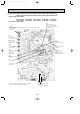
Jumper wire J1~J6
Model selection
SW1
Group number
address
SW4
Test run
SW5
Fan 100% fix
Outdoor LEV opening
fix
TH4
Discharge temperature
thermistor
TH3
Liquid temperature
thermisor
TH6
Condenser/Evaporator
temperature thermisor
CNM
When connecting A-control
Service Tool [ PAC-SK52ST ],
operation mode can be displayed
by means of 7SEG
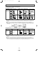
Communication power supply
D71 Voltage
developed across: 16-30V DC
–
+
52C
MC contactor
Between 1 and 3
220V~240V AC
CH
Crankcase heater
Between 1 and 3
220V~240V AC
21S4
R.V. coil
Between 1 and 3
220V~240V AC
SV
Baypass valve
solenoid coil
Between 1 and 3
220V~240V AC
MF4, MF3
(MF4 is only for PUH-P4VGAA, PU-P4VGAA, PUH-P4~P6YGAA and PU-P4~P6YGAA)
Connect to fan motor
Between 1 and 3
220V~240V AC
w2
w1
w1. 21S4 is only for PUH-P1~P4VGAA and PUH-P1.6-P6YGAA.
w2. SV is only for PUH-P5YGAA and PUH-P6YGAA.
OCT03-E-5.qxp 04.3.26 1:53 PM Page 132