
Specifications
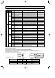


114
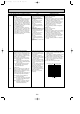
LED1(Green)
Display examples (Abnormal : E6 )
LED2(Red)
LED1
LED2
Duration
Not lighted
Continuous
Not lighted
Continuous
Not lighted
Not lighted
2 seconds
Unit
[Display]
LED1(Green)
Lighted
Lighted
Lighted
Code
— —
00,02,etc.
C4,H6,etc.
Digital display
Alternately blinking display
Operation mode
Operation mode
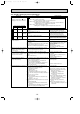
Normal condition
When the power is turned on.
When unit stops
When unit operates
LED2(Red)
Lighted
Not lighted
Lighted
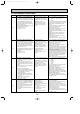
Indication of the display
Condition of LEDs
W Beep of “U” error and “F” error is be-beep.
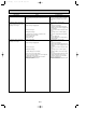
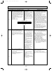
LED1
(Green)
1 blinking
LED2
(Red)
1 blinking
2 blinking
3 blinking
Indication
Error
code
F1
(4103)
F2
(4102)
F3
(5202)
F4
(4124)
F9
(4119)
FA
(4108)
F7
(4118)
F8
4 Outdoor unit error
Reverse phase detection
L3-phased open phase detection
63L connector open
49C connector open
Reverse
phase detector circuit
(Controller board) fault.
Connector 2 or more open
L2-phased open phase or
51CM connector open
Reverse phase detection, Power source and
indoor/outdoor connecting lines erroneous connection.
Detection the L3-phased open phase
3 minutes sequence detection of 63L connector open
3 minutes sequence detection of 49C connector open
Detection the signal inputless of controller board
Connector 2 or more open
3 minutes continuous detection of L2-phased open
phase or 51CM connector open
Error Name Inspection method Remarks
Inspected error when the power supply ON.
Group
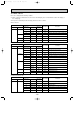
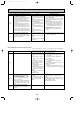
3 blinking 1 blinking
2 blinking
3 blinking
4 blinking
5 blinking
U2
(1102)
U2
(1108)
U1
(1302)
U1
UE
(1509)
UL
(1300)
Ud
(1504)
U6
(4101)
UA
(4101)
UF
(4100)
UF
(4100)
UH
(5300)
U3
(5104)
U4
(TH3:5105)
(TH6:5107)
Abnormal high discharging
temperature
Inner thermostat (49C) working
detector
Abnormal high pressure
(High pressure switch 63H worked)
Direct cut working detector
High pressure error
(ball valve closed)
Abnormal low pressure
Over heat protection
Detection the 3 minutes sequence of “Discharging thermistor
(TH4) ] 125˚C” or “Discharging thermistor (TH4) ] 135˚C
Inner thermostat working detector
1 second detection of no compressor current after
1 second of start-up
1 second detection of no compressor current
1 second detection of no compressor current within
20 seconds of Heat Start-up
Low pressure switch working detection
Detection the formula of liquid pipe thermistor (TH3) ]
heat protected temperature
Inspected error when the power supply ON.
Input circuit fault
Consider the unit abnormal when a synchronizing
signal of power supply has not been inputted for 0.5 second.
Compressor over current
(Overload) breaking
Compressor over current
(Terminal overload relay working)
Compressor over current
(start-up locked) breaking
Compressor over current
(operating locked ) switching
Current sensor error
Discharging thermistor error
detection
Outdoor thermistor error
3 seconds detection of over loaded current value
Thermal overload relay working detection
Locked current detection within 5 seconds of start-up
Locked current detection during the compressor
operation
One second detection of no compressor current at
the compressor start-up
Open/short circuit of discharging thermistor (TH4)
Open/short circuit of the liquid pipe thermistor (TH3)
or EVA/COND pipe thermistor (TH6)
•Detected by CT
•Working : 3.3MPa
•Reset : 2.6MPa
Detected by CT
Only PU(H)-P5,P6YGA
(functioning : 125i5˚C)
(return : 98i11˚C)
Only PU(H)-P•YGA(A) type
Detected by CT
Only PU(H)-P5,P6YGA
<Inspection function of units>
[For inspection, use outdoor controller board that is normally equipped.]
The blinking patterns of both LED1 (green) and LED2 (red) indicate the types of abnormality when it occurs.
Types of abnormality can be indicated in details by connecting inspectionkit for servicing A-controlled units PAC-SK52ST to
connector CNM on outdoor controller board,
Refer to page 132 for the position of connector CNM.
OCT03-E-4.qxp 04.3.26 1:52 PM Page 114