
Specifications


104
(2) Outdoor Unit
1) Check Items
• After installation of indoor and outdoor units, and tubing and electric wiring work, check that the unit is free from leaks of refrigerant, loosened
connections, and incorrect polarity.
• Check that there is no negative phase and open phase. (The F1 message for negative phase and the F2 message for open phase will flash
at digital indicator LED 1 on the outdoor substrate. If this happens, rewire correctly.)
• Measure the impedance between power terminals (Single phase: L,N,
;;
/ triple phase: L1,L2,L3,
;;
) and the ground with a 500V Merger and
check that it is 1.0MΩ or more. Do not operate the equipment if measurement is less than 1.0mΩ. *Never conduct this operation on the out-
door connection wiring terminals (S1,S2,S3) as this causes damage.
• When there is no error at the outdoor unit.
(If there is an error at the outdoor unit, it can be evaluated at LED 1 [digital display] of the outdoor substrate.)
• The stop valves are open both the liquid and gas sides.
After checking the above, execute the test run in accordance with the following.
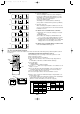
2) Test run start and finish
• Operation from the indoor unit
Execute the test run using the installation manual for the indoor unit.
• Operation from the outdoor unit.
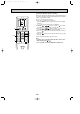
Execute settings for test run start, finish and operation mode (cooling, heating) using the DIP switch SW 4 on the outdoor substrate.
1 Set the operation mode (cooling, heating) using SW4-2.
2 Turn ON SW 4-1, The operation mode for SW 4-2 will be adhered to, and the test run will commence.
3 Turn OFF SW 4-1 to finish the test run.
• There may be a faint knocking noise emitted from the proximity of the fan during the test run. This is torque
fluctuation occurring due to control of fan revolutions. There is no problem with the product.
Note:
The SW 4-2 operation mode cannot be changed during the test run. (To change run mode, stop the equipment with SW 4-1, change
the operation mode, then restart test run with SW 4-1.)
ON
SW4
12
A Stop
B Cooling
C Operation
D Heating
A
CD
B
(Factory setting)
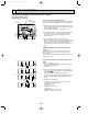
11-3. Emergency Operation
(1) Indoor unit
1. When the wired remote controller or indoor unit micro computer troubles if there is not any other wrong, emergency opera-
tion starts as the indoor control board switch (SWE) is set to ON.
During the emergency operation the indoor unit is as follows;
(1) Indoor fan high speed operation (2) Drain pump. (only provided model)
w When the remote controller cannot be used for the wireless remote controller, emergency operation is available by
operating the emergency operation switch (SW1, SW2 in the wireless remote controller receiving board) in the indoor
unit.
2. When emergency operating for COOL or HEAT, setting of the switch (SWE) in the indoor controller board and outdoor unit
emergency operation are necessary.
3. Check items and notices as the emergency operation
(1) Emergency operation cannot be used as follows;
• When the outdoor unit is something wrong.
• When the indoor fan is something wrong.
• When drain over flow protected operation is detected during self-diagnosis. (optional drain up mach.)
(2) Emergency operation will be serial operation by the power supply ON/OFF.
ON/OFF or temperature, etc. adjustment is not operated by the remote controller.
(3) Do not operate for a long time as cold air is blown when the outdoor unit starts defrosting operation during heat emer-
gency operation.
(4) Cool emergency operation must be within 10 hours at most. It may cause heat exchanger frosting in the indoor unit.
(5) After completing the emergency operation, return the switch setting, etc. in former state.
(6) As for PL-P·AA Type or PC, PK Type series, since vane does not work at emergency operation position the vane manu-
ally and slowly.
OCT03-E-4.qxp 04.3.26 1:52 PM Page 104