
Specifications


102
Remote Controller Display
Symptoms
OUTDOOR BOARD LED Display Cause
Remote controller is displaying "H0", and
operation is not possible.
After power is turned ON, "H0" is displayed
for 3 mins., then error code is displayed.
Power is turned ON, and "EE" or "EF" are
displayed after "H0" is displayed.
Display messages do not appear even
when remote controller operation switch is
turned ON (operation lamp does not light
up).
Operation display appears but soon
disappears even when remote controller
operations are executed.
• After power is turned ON, system startup lasts for about 2
mins., and "H0" is displayed (correct operation).
• Outdoor unit`s safeguard installation connector is open.
• Negative phase and open phase of outdoor unit`s power
terminal board (Single phase: L,N /triple phase: L1,L2,L3 )
• Incorrect connection of outdoor terminal board (Single phase:
L,N /triple phase: L1,L2,L3 grounding and S1,S2,S3)
• The refrigerant system of outdoor unit is different from that of
indoor unit.
• Wiring for the indoor and outdoor unit is not connected
correctly. (Polarity is wrong for S1,S2,S3)
• Remote controller transmission wire short
•There is no outdoor unit for address 0 (address is something
other than 0).
• Remote controller transmission wire burnout
• After cancellation of function selection, operation is not
possible for about 30 secs. (correct operation).
After "startup" is displayed,
only green is lit up. < 00 >
After "startup" is displayed, the
green(once) and red(once) are
blinked alternately. <F1,F2>
After "startup" is displayed, the
green(once) and red(twice) are
blinked alternately. <F3,F5,F9>
After "startup" is displayed,
only green is lit up. < 00,EE>
After "startup" is displayed, the
green(twice) and red(once) are
blinked althernately. <EA,Eb>
After "startup" is displayed,
only green is lit up. < 00 >
After "startup" is displayed,
only green is lit up. < 00 >
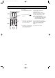
In case of digital display, < > is displayed.
* Press the remote controller`s “CHECK” button twice consecutively to be able to run a self diagnosis. See the chart below for content of
error code displays.
LCD
Nonconformity Content
P1
P2
P4
P5
P6
P8
P9
Abnormality of room temperature thermistor (TH1).
Abnormality of pipe temperature thermistor/Liquid (TH2)
Abnormality of drain sensor (DS)
Malfunction of drain-up machine
Freezing/overheating protection is working
Abnormality of pipe temperature
Abnormality of pipe temperatuer thermistor/Cond./Eva. (TH5)
LCD
Nonconformity Content
E0~E5
E6~EF
U0~UL
F1~F9
----
FFFF
Abnormality of the signal transmission between remote
controller and indoor unit.
Abnormality of the signal transmission between indoor unit and
outdoor unit.
Abnormality in outdoor unit.
Abnormality in outdoor unit.
No trouble generated in the past.
No corresponding unit.
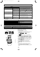
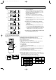
LED 1 (microcomputer power supply)
LED 2 (remote controller feed)
LED 3 (indoor and outdoor signals)
Displays the ON/OFF of power for control. Check that this is lit during normal use.
Displays the ON/OFF of feed to wired remote controller. Is only lit for indoor unit linked to outdoor
unit with address "00".
Displays signal between indoor and outdoor units. Check that this is flashing during normal use.
See the chart below for details of the LED displays (LED 1,2,3) on the indoor substrate.
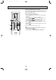
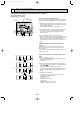
Wireless remote controller type
Operating procedures
1 Turn on the main power to the unit.
2 Set the Nrm/Set selector switch (on the back of the con-
troller) to “Set”.
A The , and begin to blink.
3 Press the button.
B and current operation mode are displayed.
4 Press the ( ) button to activate mode,
then check whether cool air is blown out from the unit.
5 Press the ( ) button to activate mode,
then check whether warm air is blown out from the unit.
6 Press the button and check whether strong air is
blown out from the unit.
7 Press the button and check whether the auto
vane operates properly.
8 Press the ON/OFF button to stop the trial run.
9 After trial run is complete, set the Nrm/Set selector
switch to “Nrm”.
Note:
• Point the remote controller toward the inside unit’s
receiver while following steps 3 though 8.
• It is not possible to run the unit in BLOW, DRY or AUTO
mode.
Nrm Set
92
ON/OFF
CHECK
ADDRESS
UNIT No.
FUNCTION No.
SELECTION No.
AM
PM
RESET
AM
PM
TEST RUN
FUNCTION
˚C
MODE FAN
VANE
TEMP.
START
STOP
HR.
MIN.
A
B
8
4
5
6
7
3
FUNCTION
TEST RUN
CHECK
MIN.
TEST RUN
MODE
COOL
MODE
FAN
VANE
HEAT
OCT03-E-4.qxp 04.3.26 1:52 PM Page 102