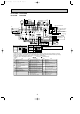
OCT03-E-1.qxp 04.3.26 1:38 PM Page 1 SPLIT-TYPE, HEAT PUMP AIR CONDITIONERS SPLIT-TYPE, AIR CONDITIONERS SERVICE TECHNICAL GUIDE R407C [Model names] [Service Ref] PEAD–P·EA PLH–P·KAH PLA–P·KA PCH–P·GAH PCA–P·GA PCA–P·HA PKH–P·GALH PKA–P·GAL PKH–P·FALH PKA–P·FAL PKA–P·FAL-H PSH–P·GAH PSA–P·GA PMH–P·BA PLH–P·AAH.UK PLA–P·AA(.UK) PLH–P·KAH.UK PLA–P·KA(.UK) PEHD–P·EAH.UK PEAD–P·EA.
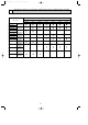
OCT03-E-1.qxp 04.3.26 1:38 PM 1 Page 2 PAIRING TABLE OF THE INDOOR AND OUTDOOR UNITS Outdoor unit [PUH/PU] Indoor unit OC180 REVISED EDITION-A P1.6GA PLH–P·KAH PLA–P·KA PCH–P·GAH PCA–P·GA PKH–P·GALH PKA–P·GAL PKH–P·FALH1 OC182 REVISED EDITION-B REVISED EDITION-B OC175 PSH–P·GAH OC212 PLH–P·AAH.UK PLA–P·AA.UK PLH–P·KAH.UK PLA–P·KA.UK P3GA P4GA P5GA P6GA — — — — — — — — OC176 REVISED EDITION-B PMH–P·BA P2.
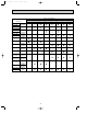
OCT03-E-1.qxp 04.3.26 1:38 PM Page 3 Outdoor unit [PUH/PU] Indoor unit OC261 REVISED EDITION-A Service ref. PCH–P·GAH1 PCA–P·GA1 PKH–P·GALH1 PKA–P·GAL1 PKH–P·FALH2 PKA–P·FAL2 PSH–P·GAH1 PSA–P·GA1 PMH–P·BA1 PMH–P·BA2 PLA–P·AA PLA–P·KA PCA–P·HA PLH–P·AAH1.UK PLA–P·AA1.UK PLH–P·KAH1.UK PLA–P·KA1.UK PEHD–P·EAH.UK PEAD–P·EA.UK P1GAA1.UK P1.6GAA1.UK P2GAA1.UK P2.5GAA1.UK P3GAA1.UK P4GAA1.UK P5GAA1.UK P6GAA1.
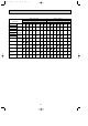
OCT03-E-1.qxp 04.3.26 1:38 PM Page 4 Indoor unit Service ref. PCH–P·GAH1 PCA–P·GA1 PKH–P·GALH1 PKA–P·GAL1 PKH–P·FALH2 PKA–P·FAL2 PSH–P·GAH1 PSA–P·GA1 PMH–P·BA1 PMH–P·BA2 PLA–P·AA PLA–P·KA PCA–P·HA PEHD–P·EAH.UK PEAD–P·EA.UK Outdoor unit [PUH] Outdoor unit [PU] OC285 OC298 P1.6GAA P2GAA P2.5GAA P3GAA P4GAA P5GAA P6GAA P1.6GAA P2GAA P2.
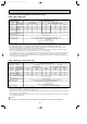
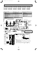
OCT03-E-1.qxp 04.3.26 1:38 PM 2 Page 5 SPECIFICATIONS FOR ELECTRICAL WORK A Power supply for outdoor unit B Main switch/fuse(purchased locally)for outdoor unit C Power supply wiring for outdoor unit D Outdoor unit E Indoor unit F Connection wiring for indoor/outdoor units(polarity) G Remote controller H Connection wiring for indoor/remote controller(no polarity) I Grounding 2-1.
OCT03-E-1.qxp 04.3.26 1:38 PM Page 6 2-2. Field electrical wiring(power wiring specifications) PU(H)-P•GA, PU(H)-P•GA1 Wiring Models (Outdoor unit) indoor unit power supply Phase Outdoor unit Frequency & Voltage Power supply Indoor unit (A) Input capacity Outdoor unit (A) Main switch/Fuse Heater Wire No. Power supply Size (e) Outdoor unit Wire No. Power supply Size (e) Indoor unit/Outdoor unit connecting Wire No. o size (e) Remote controller-indoor unit connecting Wire No.
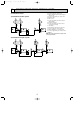
OCT03-E-1.qxp 04.3.26 1:38 PM 3 Page 7 WIRING DIAGRAM PLH-P1.6KAH PLH-P2KAH PLH-P2.5KAH PLA-P1.6KA PLA-P2KA PLA-P2.5KA PLA-P1.6KA1 PLA-P2KA1 PLA-P2.5KA1 OUTDOOR UNIT PU(H)-P1.6~2.5VGAA PU(H)-P1.6~2.5VGAA.UK PU(H)-P1.6~2.5VGAA1.UK S1 PU(H)-P1.6~2.5VGA POWER SUPPLY S2 ~(1PHASE) S3 220-240V 50Hz 1 3 3 BLK 5 X1 X3 CN25 FC X4 X1 X3 2 VANE HEATER REMOTE CN24 CONTROLLER POSITION (YLW) CN22 (BLU) CN23 (GRN) 1 2 1 2 1 2 1 88H SW1 MODELS Manufacture Service board 1 2 3 4 5 PLH-1.6~2.
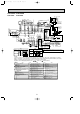
OCT03-E-1.qxp 04.3.26 1:38 PM Page 8 PLH-P3KAH PLH-P4KAH PLA-P3KA PLA-P4KA TB1 OUTDOOR UNIT L1 S1 GRILLE LS MV 1 2 3 L2 S3 L3 P.B CN2S(WHT) MF S2 2 1 H2 DC14V ZNR YLW 1 ORN 2 BRN 3 CONTROLLER BOARD OUTDOOR UNIT CN02 (WHT) CN01 (BLU) DP C POWER SUPPLY 3N~ (3PHASE 4WIRES) 380-415V 50Hz TB4 3 2 1 5 10 1 6 2 7 N F1 S1 S2 S3 S1 S2 S3 1 2 X3 FS1 CN25 CN32 LED3 LED2 LED1 SW2 CN2L X1 WIRELESS J15 J14 J13 J12 J11 J24 J23 J22 J21 D.
OCT03-E-1.qxp 04.3.26 1:38 PM Page 9 PLH-P5KAH PLH-P6KAH PLA-P5KA PLA-P6KA GRILLE LS P.B CN2S(WHT) MF MV 1 2 3 2 7 2 1 H2 DC14V ZNR 1 2 3 3 2 1 5 10 1 6 DP C F1 TB4 S1 S2 S3 YLW ORN BRN OUTDOOR UNIT CN01 (BLU) CONTROLLER BOARD CN02 (WHT) TB1 OUTDOOR UNIT S1 S2 S3 1 2 W.B 1 3 5 1 2 LED3 LED2 LED1 D.
OCT03-E-1.qxp 04.3.26 1:38 PM PCH-P2GAH PCH-P2GAH1 PCA-P2GA PCA-P2GA1 SYMBOL P.B F1 ZNR I.B CN2L CN32 CN41 SW1 SW2 SWE X1 X4 FC LED1 LED2 LED3 C MF Page 10 PCH-P2.5GAH PCH-P2.5GAH1 PCA-P2.5GA PCA-P2.5GA1 PCH-P3GAH PCH-P3GAH1 PCA-P3GA PCA-P3GA1 PCH-P4GAH PCH-P4GAH1 PCA-P4GA PCA-P4GA1 SYMBOL MV DP DS TB2 TB4 TB5 INDOOR UNIT 2 1 DC14V 3 2 1 (OPTION) D.U.
OCT03-E-1.qxp 04.3.26 1:38 PM Page 11 PCA-P3HA PCA-P5HA INDOOR UNIT ORN RED BLK BLU YLW WHT C2 1 1 YLW YLW GRY FAN 1 3 5 7 (WHT) X6 X5 X4 SW1 Manufacture Service board MODELS 1 2 3 4 5 1 2 3 4 ON OFF PCA-P3HA J21 J22 J23 J24 1 2 3 4 PCA-P5HA 1 2 SW2 Manufacture Service board J21 J22 J23 J24 SYMBOL F1 ZNR I.
OCT03-E-1.qxp 04.3.26 1:38 PM Page 12 PKH-P1.6GALH PKH-P2GALH PKH-P1.6GALH1 PKA-P1.6GAL PKA-P2GAL PKA-P1.6GAL1 INDOOR UNIT 2 1 3 2 1 YLW ORN BRN 1 3 5 FAN (WHT) POWER 1 3 5 CN03 (RED) BLK WHT RED WHT BLK 3 2 1 C F1 DC14V ZNR CONT.BOARD CN02(WHT) OUTDOOR CN01(BLU) CN41 S1 S2 S3 S1 S2 S3 S1 S2 S3 TB1 6 L1 L2 L3 N PE MV PE WIRELESS CN90 CN32 (WHT) J15 J14 J13 J12 J11 J24 J23 J22 J21 D.SENSOR CN31 (WHT) HEATER INTAKE LIQUID CN24 CN20 CN21 (YLW) (RED) (WHT) 1 2 1 2 3 PKH-P1.
OCT03-E-1.qxp 04.3.26 1:38 PM PKH-P2.5FALH PKH-P2.5FALH1 PKH-P2.5FALH2 PKA-P2.5FAL PKA-P2.5FAL1 PKA-P2.5FAL2 Page 13 PKH-P3FALH PKH-P3FALH1 PKH-P3FALH2 PKA-P3FAL PKA-P3FAL1 PKA-P3FAL2 PKH-P4FALH PKH-P4FALH1 PKH-P4FALH2 PKA-P4FAL PKA-P4FAL1 PKA-P4FAL2 INDOOR UNIT 2 1 MF 3 2 1 1 2 3 BLK WHT YLW ORN BRN RED WHT BLK C I.B POWER CN03 1 3 5 (RED) 1 3 5 FAN (WHT) DC14V F1 ZNR CONT.
OCT03-E-1.qxp 04.3.26 1:38 PM Page 14 PKA-P2.5FAL-H PKA-P3FAL-H PKA-P4FAL-H INDOOR UNIT P.B CN2S(WHT) 2 1 F1 DC14V ZNR MF H2 1 2 3 3 2 1 BLK WHT YLW ORN BRN BLU BLU I.B RED WHT BLK C POWER 1 3 CN03 1 3 5 1 3 5 FAN D.HEATER (RED) (WHT) CNC (RED) FC X4 CONT.
04.3.26 1:38 PM PSH-P3GAH PSH-P3GAH1 PSA-P3GA PSA-P3GA1 PSH-P4GAH PSH-P4GAH1 PSA-P4GA PSA-P4GA1 PSH-P5GAH PSH-P5GAH1 PSA-P5GA PSA-P5GA1 NAME SYMBOL INDOOR CONTROLLER BOARD CONNECTOR(LOSSNAY) CONNECTOR(REMOTE SWITCH) CONNECTOR(HA TERMINAL-A) POWER SUPPLY(I.B) POWER SUPPLY(R.B) TRANSMISSOION(INDOOR • OUTDOOR) JUMPER WIRE(MODEL SELECTION) JUMPER WIRE(CAPACITY CORD) SWITCH(EMERGENCY OPERATION) RELAY(LOUVER) RELAY(FAN MOTOR) RELAY(FAN MOTOR) RELAY(FAN MOTOR) I.
OCT03-E-1.qxp 04.3.26 1:38 PM Page 16 PMH-P1BA PMH-P1.6BA PMH-P2BA PMH-P1BA1 PMH-P1.6BA1 PMH-P2BA1 PMH-P1BA2 PMH-P1.6BA2 PMH-P2BA2 [LEGEND] DP DS MF MV TB4 TB5 TH1 NOTES: 1.Since the outdoor side electric wiring may change be sure to check the outdoor unit electric wiring for servicing. 2.Indoor and outdoor connecting wires are made with polarities, make wiring matching terminal numbers(S1, S2, S3). 3.Symbols used in wiring diagram above are, :Connector, :Terminal (block).
OCT03-E-1.qxp 04.3.26 1:38 PM Page 17 PLH-P3AAH.UK PLH-P4AAH.UK PLH-P5AAH.UK PLH-P6AAH.UK PLH-P3AAH1.UK PLH-P4AAH1.UK PLH-P5AAH1.UK PLH-P6AAH1.UK SYMBOL P.B F1 ZNR I.
OCT03-E-1.qxp 04.3.26 1:38 PM Page 18 PLA-P3AA PLA-P4AA PLA-P5AA PLA-P6AA PLA-P3AA.UK PLA-P4AA.UK PLA-P5AA.UK PLA-P6AA.UK PLA-P3AA1.UK PLA-P4AA1.UK PLA-P5AA1.UK PLA-P6AA1.UK SYMBOL P.B F1 ZNR I.
OCT03-E-1.qxp 04.3.26 1:38 PM Page 19 PLH-P1.6KAH.UK PLH-P2KAH.UK PLH-P2.5KAH.UK PLH-P1.6KAH1.UK PLH-P2KAH1.UK PLH-P2.5KAH1.UK OUTDOOR UNIT PU(H)-P1.6, 2, 2.5VGA(1) PU(H)-P1.6, 2, 2.5VGAA.UK POWER SUPPLY ~/N(1PHASE) 220-240V 50Hz S1 S2 S3 P.B W.B REMOTE CONTROLLER 1 3 3 D.HEATER 1 CNC (RED) 3 BLK 5 7 WHT BRN YLW 1 3 ORN BLU RED YLW RED D.U.M 1 CNP (BLU) X3 3 OUTDOOR UNIT CN01 (BLU) PUH-P1.6, 2, 2.5YGA(1) PU(H)-P1.6, 2, 2.5YGAA.
OCT03-E-1.qxp 04.3.26 1:38 PM Page 20 PLA-P1.6KA.UK PLA-P2KA.UK PLA-P2.5KA.UK PLA-P1.6KA1.UK PLA-P2KA1.UK PLA-P2.5KA1.UK OUTDOOR UNIT PU(H)-P1.6, 2, 2.5VGA(1) PU(H)-P1.6, 2, 2.5VGAA.UK POWER SUPPLY ~/N(1PHASE) 220-240V 50Hz S1 S2 S3 8 MF REMOTE CONTROLLER 1 3 3 D.
OCT03-E-1.qxp 04.3.26 1:38 PM Page 21 PEHD-P1.6EAH.UK PEHD-P1.6EAH1.UK PEHD-P4EAH.UK PEHD-P4EAH1.UK PEHD-P2EAH.UK PEHD-P2EAH1.UK PEHD-P5EAH.UK PEHD-P5EAH1.UK PEHD-P2.5EAH.UK PEHD-P3EAH.UK PEHD-P2.5EAH1.UK PEHD-P3EAH1.UK PEHD-P6EAH.UK PEHD-P6EAH1.UK PEAD-P1.6EA.UK PEAD-P1.6EA1.UK PEAD-P4EA.UK PEAD-P4EA1.UK PEAD-P2EA.UK PEAD-P2EA1.UK PEAD-P5EA.UK PEAD-P5EA1.UK PEAD-P2.5EA.UK PEAD-P2.5EA1.UK PEAD-P6EA.UK PEAD-P6EA1.UK 21 PEAD-P3EA.UK PEAD-P3EA1.
OCT03-E-1.qxp 04.3.26 1:38 PM Page 22 PUH-P1.6 VGA PUH-P2VGA PUH-P2.5VGA PUH-P 3VGA PUH-P2.
OCT03-E-1.qxp 04.3.26 1:38 PM Page 23 PUH-P1.6YGA PUH-P2YGA PUH-P2.5YGA PUH-P3YGA PUH-P4YGA PUH-P5YGA PUH-P6YGA PUH-P2.
OCT03-E-1.qxp 04.3.26 1:38 PM Page 24 PU-P1.6VGA PU-P2VGA PU-P2.5VGA PU-P3VGA PU-P2.
OCT03-E-1.qxp 04.3.
OCT03-E-1.qxp 04.3.26 1:38 PM Page 26 PUH-P1.6VGAA PUH-P2VGAA PUH-P2.
OCT03-E-1.qxp 04.3.
OCT03-E-1.qxp 04.3.26 1:39 PM Page 28 PU-P1.6VGAA PU-2VGAA PU-2.
OCT03-E-1.qxp 04.3.
OCT03-E-1.qxp 04.3.26 1:39 PM PUH-P1VGAA.UK PUH-P3VGAA.UK PUH-P1VGAA1.UK PUH-P3VGAA1.UK Page 30 PUH-P1.6VGAA.UK PUH-P2VGAA.UK PUH-P2.5VGAA.UK PUH-P4VGAA.UK PUH-P1.6VGAA1.UK PUH-P2VGAA1.UK PUH-P2.5VGAA1.UK PUH-P4VGAA1.
OCT03-E-2.qxp 04.3.26 1:48 PM Page 31 PUH-P1.6YGAA.UK PUH-P4YGAA.UK PUH-P1.6YGAA1.UK PUH-P4YGAA1.UK PUH-P2YGAA.UK PUH-P5YGAA.UK PUH-P2YGAA1.UK PUH-P5YGAA1.UK PUH-P2.5YGAA.UK PUH-P3YGAA.UK PUH-P6YGAA.UK PUH-P2.5YGAA1.UK PUH-P3YGAA1.UK PUH-P6YGAA1.
OCT03-E-2.qxp 04.3.26 1:48 PM Page 32 PU-P1.6VGAA.UK PU-P2VGAA.UK PU-P2.5VGAA.UK PU-P3VGAA.UK PU-P4VGAA.UK PU-P1.6VGAA1.UK PU-P2VGAA1.UK PU-P2.5VGAA1.UK PU-P3VGAA1.UK PU-P4VGAA1.
OCT03-E-2.qxp 04.3.26 1:48 PM Page 33 PU-P1.6YGAA.UK PU-P2YGAA.UK PU-P2.5YGAA.UK PU-P3YGAA.UK PU-P4YGAA.UK PU-P5YGAA.UK PU-P6YGAA.UK PU-P1.6YGAA1.UK PU-P2YGAA1.UK PU-P2.5YGAA1.UK PU-P3YGAA1.UK PU-P4YGAA1.UK PU-P5YGAA1.UK PU-P6YGAA1.
OCT03-E-2.qxp 4 04.3.26 1:48 PM Page 34 REFRIGERANT SYSTEM DIAGRAM 4-1. Checking operation statuses Measurement points and items •The table and diagrams below show the measurement item for each measurement point, and the pressure and temperature near the JIS standard operating conditions. •Measure the temperature and pressure of each part by following the descriptions in the table.
OCT03-E-2.qxp 04.3.26 1:48 PM Page 35 4-2. Refrigerant system Diagram 4-2-1.
OCT03-E-2.qxp 04.3.26 1:48 PM Page 36 4-2-2. Outdoor unit PUH-P1.6VGA PUH-P2VGA PUH-P2.5VGA PUH-P2.5VGA1 PUH-P3VGA PUH-P1.6YGA PUH-P2YGA PUH-P2.5YGA PUH-P2.5YGA1 PUH-P3YGA High pressure protect switch Refrigerant pipe 4-way valve 15.
OCT03-E-2.qxp 04.3.26 1:48 PM Page 37 PU-P1.6VGA PU-P2VGA PU-P2.5VGA PU-P2.5VGA1 PU-P3VGA PU-P3YGA High pressure protect switch Refrigerant pipe 15.88A({5/8") Ball valve (with heat insulator) Strainer Outdoor unit Outdoor heat exchanger Thermistor (TH6) Flexible tube Service port Thermistor (TH3) Service port Flared connection Thermistor(TH4) Accumulator Strainer Compressor Drier Strainer Refrigerant pipe Ball valve 9.
OCT03-E-2.qxp 04.3.26 1:48 PM Page 38 PUH-P1.6VGAA PUH-P2VGAA PUH-P2.5VGAA PUH-P3VGAA PUH-P3YGAA Ball valve Refrigerant pipe 15.88A({5/8") (with heat insulator) 4-way valve High pressure protect switch Outdoor unit Outdoor heat exchanger Strainer Thermistor (TH6) #50 Service port Flexible tube Service port Flared connection Thermistor (TH3) Muffler Thermistor(TH4) Distributor with strainer #50 Accumulator Compressor Refrigerant pipe 9.
OCT03-E-2.qxp 04.3.26 1:48 PM Page 39 PU-P1.6VGAA PU-P2VGAA PU-P2.5VGAA PU-P3VGAA PU-P3YGAA High pressure protect switch Ball valve Refrigerant pipe 15.88A({5/8") (with heat insulator) Strainer #50 Outdoor unit Outdoor heat exchanger Thermistor (TH6) Flexible tube Service port Thermistor (TH3) Service port Flared connection Thermistor(TH4) Distributor with strainer #50 Accumulator Compressor Strainer #100 Strainer #100 Refrigerant pipe Stop valve 9.
OCT03-E-2.qxp 04.3.26 1:48 PM Page 40 PUH-P1VGAA.UK PUH-P1.6VGAA.UK PUH-P1.6YGAA.UK PUH-P1VGAA1.UK PUH-P1.6VGAA1.UK PUH-P1.6YGAA1.UK PUH-P2VGAA.UK PUH-P2YGAA.UK PUH-P2VGAA1.UK PUH-P2YGAA1.UK Refrigerant pipe Ball valve P1···12.7A({1/2") 4-way valve P1.6~P3···15.88A({5/8") (with heat insulator) Strainer High pressure protect switch PUH-P2.5VGAA.UK PUH-P2.5YGAA.UK PUH-P2.5VGAA1.UK PUH-P2.5YGAA1.
OCT03-E-2.qxp 04.3.29 10:02 AM PU-P1.6VGAA.UK PU-P1.6YGAA.UK PU-P1.6VGAA1.UK PU-P1.6YGAA1.UK Page 41 PU-P2VGAA.UK PU-P2YGAA.UK PU-P2VGAA1.UK PU-P2YGAA1.UK PU-P2.5VGAA.UK PU-P2.5YGAA.UK PU-P2.5VGAA1.UK PU-P2.5YGAA1.UK High pressure protect switch Refrigerant pipe 15.88A({5/8") Ball valve (with heat insulator) Strainer PU-P3VGAA.UK PU-P3YGAA.UK PU-P3VGAA1.UK PU-P3YGAA1.
OCT03-E-2.qxp 5 04.3.26 1:48 PM Page 42 HOW TO CHECK THE PARTS 5-1. Indoor unit 1 Common parts Parts name Check points Room temperature thermistor (TH1) Disconnect the connector then measure the resistance using a tester. (Surrounding temperature 10:~30:) Pipe temperature thermistor (TH2) Condenser/evaporator temperature thermistor (TH5) Drain sensor Normal Abnormal 4.3k"~9.6k" Open or short (Refer to below for a detail.) Measure the resistance between the terminals using a tester.
OCT03-E-2.qxp 04.3.26 1:48 PM Page 43 2 PLH-P1.6, P2, P2.5, P3, P4, P5, P6KAH PLA-P1.6, P2, P2.5, P3, P4, P5, P6KA PLA-P1.6, P2, P2.5KA1 PLH-P1.6, P2, P2.5KAH.UK PLA-P1.6, P2, P2.5KA.UK Parts name Check points Fan motor Relay connector 1 Red 2 White 3 Black Measure the resistance between the terminals using a tester. (Winding temperature 20:) Normal 2 Motor terminal or Relay connector 3 Red–Black 87.2" White–Black 104.
OCT03-E-2.qxp 04.3.26 1:48 PM Page 44 3 PCH-P2, P2.5, P3, P4, P5, P6GAH PCA-P2, P2.5, P3, P4, P5, P6GA Parts name Check points Fan motor Relay connector 1 Red 2 White 3 Black 1 2 3 Protector OFF:130i5: ON :80i20: Measure the resistance between the terminals using a tester. (Winding temperature 20:) Normal Motor terminal or Relay connector P2 P2.5, P3 P4 P5, P6 Red–Black 70.6" 45.0" 43.7" 20.4" White–Black 69.6" 44.8" 55.3" 20.
OCT03-E-2.qxp 04.3.26 1:48 PM Page 45 4 PCA-P3HA PCA-P5HA Parts name Check points Fan motor Relay connector Protector Measure the resistance between the terminals using a tester. (Winding temperature 20:) Normal Connector White Orange PCH-P3HA PCH-P5HA White–Black 140.5" 75.6" Red Brown–Blue 15.4" 36.7" Yellow Blue–Yellow 28.5" 23.6" Blue Yellow–Red 80.4" 47.8" Abnormal Open or short Protector OPEN : 135i5: CLOSE : 95i15: Black 5 PKH-P1.6, P2GALH PKA-P1.
OCT03-E-2.qxp 04.3.26 1:48 PM Page 46 6 PKH-P2.5, P3, P4FALH PKA-P2.5, P3, P4FAL PKA-P2.5, P3, P4FAL-H Parts name Check points Fan motor Relay connector 1 Red 2 White 3 Black 1 2 3 Protector OFF:130i5: ON :80i20: 4 Orange Red 2 Pink Normal Motor terminal or Relay connector P2.5, P3 P4 Red–Black 99.5" 62.6" White–Black 103.9" 74.0" Abnormal Open or short Measure the resistance between the terminals using a tester.
OCT03-E-2.qxp 04.3.26 1:48 PM Page 47 7 PSH-P3, P4, P5, P6GAH PSA-P3, P4, P5, P6GA Parts name Check points Measure the resistance between the terminals using a tester. (Winding temperature 20:) Fan motor P3, P4 Protector White Normal Motor terminal or Relay connector P3 P4 Black White–Black 112.1" 91.5" Blue Black–Blue 22.1" 18.0" Blue–Yellow 41.0" 29.6" Black–Red 178.5" 174.
OCT03-E-2.qxp 04.3.26 1:48 PM Page 48 9 PLH-P3, P4, P5, P6AAH PLA-P3, P4, P5, P6AA Parts name Check points Vane motor Measure the resistance between the terminals using a tester. (Surrounding temperature 20:) Fan motor Relay connector 1 Red 2 White 3 Black Normal Abnormal 15k" Open or short Measure the resistance between the terminals using a tester. (Surrounding temperature 20:) Normal 2 Motor terminal or Relay connector 3 Red–Black 87.2" 28.7" White–Black 104.1" 41.
OCT03-E-2.qxp 04.3.26 1:48 PM Page 49 5-2. Outdoor unit PUH-P1.6, P2, P2.5, P3VGA PU-P1.6, P2, P2.5, P3VGA PUH-P1.6, P2, P2.5, P3, P4, P5, P6YGA PU-P2, P2.5, P3, P4, P5, P6YGA Check points Parts name Liquid temperature thermistor (TH3) Discharge temperature thermistor (TH4) Condenser/evaporator temperature thermistor (TH6) FAN MOTOR(MF) Black Orange Red White Disconnect the connector then measure the resistance using a tester. (Surrounding temperature 10:~30:) Normal Abnormal TH3 4.3k"~9.
OCT03-E-2.qxp 04.3.26 1:48 PM Page 50 PU(H)-P1, P1.6, P2, P2.5, P3VGAA.UK PU(H)-P1.6, P2, P2.5, P3, P4, P5, P6YGAA.UK Check points Parts name Liquid temperature thermistor (TH3) Discharge temperature thermistor (TH4) Condenser/evaporator temperature thermistor (TH6) FAN MOTOR(MF) Black Orange Red White Disconnect the connector then measure the resistance using a tester. (Surrounding temperature 10:~30:) Normal TH3 4.3k"~9.6k" TH4 160k"~410k" TH6 4.3k"~9.
OCT03-E-2.qxp 04.3.26 1:48 PM Page 51 PU(H)-P1.6, 2, 2.5, 3VGAA PU(H)-P3, 4, 5, 6YGAA Check points Parts name Liquid temperature thermistor (TH3) Discharge temperature thermistor (TH4) Condenser/evaporator temperature thermistor (TH6) FAN MOTOR(MF) Disconnect the connector then measure the resistance using a tester. (Surrounding temperature 10:~30:) Normal Abnormal TH3 160k"~410k" TH4 4.3k"~9.6k" TH6 4.3k"~9.6k" (Refer to the next pege for a detail.
OCT03-E-2.qxp 04.3.26 1:48 PM Page 52 COMPRESSOR TECHNICAL DATA Unit PUH-P1.6VGA PU-P1.6VGA Compressor model (at 20°C) PUH-P1.6YGA PUH-P2VGA PU-P2VGA PUH-P2YGA RE277VHSM RE277YFKM NE38VMJM NE38YEJM NE41VMJM NE41YEJM 1.80 10.8 0.85 5.21 0.79 5.00 3.00 10.8 2.15 5.21 2.19 5.00 — 10.8 — 5.21 — 5.
OCT03-E-2.qxp 04.3.26 1:48 PM Page 53 Check points Parts name COMPRESSER (MC) 1Winding resistance(") Mersure the resistance between the terminals using a tester. (Surrouding temperature 20:) Normal Terminals PU(H)-P1.6VGAA PU(H)-P2VGAA PU(H)-P2.5VGAA PU(H)-P3VGAA PU(H)-P3YGAA Abnormal RE277VHSM NE36VMJMT NE41VMJMT NE52VNJMT NE52YDKMT U-V(R-C) 1.80" 0.89" 0.87" 0.64" 3.59" U-W(S-C) 3.00" 2.03" 2.22" 1.67" 3.59" Open or short W-U — — — — 3.59" (P1.6~P2.
OCT03-E-2.qxp 04.3.26 1:48 PM Page 54 Thermistor for lower temperature Liquid temperature thermistor(TH3) Condenser/evaporator temperature thermistor(TH6) < Thermistor for lower temperature > 50 40 Rt=15exp { 3480( 0: 10: 20: 25: 30: 40: 1 273+t Resistance (K") Thermistor R0=15k' ± 3% Fixed number of B=3480K ± 2% 1 )} 273 15k' 9.6k' 6.3k' 5.2k' 4.3k' 3.
OCT03-E-2.qxp 04.3.26 1:48 PM Page 55 Linear expansion valve ① Operation summary of the linear expansion valve. • Linear expansion valve open/close through stepping motor after receiving the pulse signal from the indoor controller board. • Valve position can be changed in proportion to the number of pulse signal.
OCT03-E-2.qxp 04.3.26 1:48 PM Page 56 ➂ Trouble shooting Problem Operation circuit failure of the micro processor. Check point Remove the connector from the controller board and connect diagnostic 6 LEDs. 5 4 3 2 1 Corrective measure Exchange the indoor controller board at drive circuit failure. 1k" LED Pulse signal will be sent out for 10 seconds as soon as the main switch is turn on. If there is LED with lights on or lights off, it means the operation circuit is abnormal.
OCT03-E-2.qxp 6 04.3.26 1:48 PM Page 57 MICROPROCESSOR CONTROL Fuse Fan control Outdoor fan Fuse DC/DC converter Relay Crankcase heater Communication link DC5V for Microprocessor Relay 4-way valve, Solenoid valve Driver LEV Compressor Electromagnetic contactor Current detection AC220, 230, 240V AC380, 440, 415V Connecting terminal Power supply bed between the indoor and outdoor unit terminal bed 6-1.
OCT03-E-2.qxp 04.3.26 1:48 PM Page 58 6-2. System construction (1) System construction A-control model which just wires the connecting line between the indoor and outdoor unit and supply the power is applicable to any models of standard (1:1), twin and triple. (Refer to 2 Start-up system.) Standard 1:1 Synchronized twin. Triple Outdoor unit; (00)...
OCT03-E-2.qxp 04.3.
OCT03-E-2.qxp 04.3.26 1:48 PM Page 60 (3) The waveforms of from remote controller communications The following graphs are the examples for measuring waveforms on the wirings of remote controlled transmission at the terminal block for remote controller. a) A measuring example in the sequence of startup b) A measuring example during normal stop 7.5 seconds Transmission from remote controller 7.
OCT03-E-3.qxp 04.3.26 1:50 PM Page 61 (4) The waveforms of communications between indoor and outdoor units The following graphs are the examples for measuring waveforms on the wirings of connecting indoor and outdoor units at between S2 and S3 of the outdoor terminal block TB1.
OCT03-E-3.qxp 04.3.26 1:50 PM Page 62 (5) Start-up system A control unit is applicable to any models of standard (1:1), twin and triple without switch setting according to carrying out the below process automatically when the power is supplied.
OCT03-E-3.qxp 04.3.26 1:50 PM Page 63 Function/control specifications 4-way ceiling cassette Item PLH-P•KAH(.UK) PLH-P•AAH.UK PLA-P•KA(.UK) Function / specification Fan 1-way ceiling Ceiling cassette suspended PMH-P•BA PLA-P•AA(.UK) Number of fan speed 4 4 Drive method Pulsation Pulsation Floor Ceiling standing concealed PCH-P•GAH PKH-P•GALH PKH-P•FALH PSH-P•GAH PEHD-P•EAH.UK PCA-P•GA 4 Wall mounted 4 PKA-P•GAL 4 PKA-P•FAL PSA-P•GA 2 2 PEAD-P•EA.
OCT03-E-3.qxp 7 04.3.26 1:50 PM Page 64 INDOOR UNIT CONTROL 7-1. COOL operation Control modes 1. Compressor Control details 1-1. Thermoregulating function (Function to prevent restarting for 3 minutes) • Room temp. ] desired temp. +1:(w2)···Compressor ON • Room temp. [ desired temp.
OCT03-E-3.qxp 04.3.26 1:50 PM Page 65 Control modes 3. Drain pump Remarks Control details 3-1. Drain pump control •Always drain pump ON during the COOL and DRY mode operation. (Regardless of the compressor ON/ OFF) •When the operation mode has changed from the COOL or DRY to the others (including Stop), OFF the control after the drain pump ON for 3 minutes. Drain sensor function • Energize drain sensor at a fixed voltage for a fixed duration.
OCT03-E-3.qxp 04.3.26 1:50 PM Page 66 7-2. DRY operation Control modes 1. Compressor Remarks Control details 1-1. Thermoregulating function (Function to prevent restarting for 3 minutes) Setting the compressor operation time by the thermoregulating signal and the room temperature (TH1). Thermoregulating signal ON Room temp. ] desired temp. +1: Thermoregulating signal OFF Room temp. [ desired temp. 3 min. passed since starting operation Room temp. Thermoregulating signal ON Over 18: Room temp.
OCT03-E-3.qxp 04.3.26 1:50 PM Page 67 7-4. HEAT operation Control modes 1. Compressor Remarks Control details 1-1. Thermoregulating function (Function to prevent restarting for 3 minutes) ✻1 The thermoregulating function is •Room temp. [ desired temp.-1: ···Compressor ON provided in the outdoor unit. •Room temp. ] desired temp. ···Compressor OFF The indoor unit transmits the indoor room temp. and set temp. data to outdoor unit, then the outdoor unit controls thermoregulation. 1-2.
OCT03-E-3.qxp 04.3.26 1:50 PM Page 68 Control details Control modes 3. Fan Remarks Controlled by the remote controller (4-speed or 2-speed) Give priority to under-mentioned controlled mode 3-1. Hot adjuster mode 3-2. Preheating exclusion mode 3-3. Thermo OFF mode (When the compressor off by the thermoregulating) 3-4. Cool air prevention mode (Defrosting mode) 3-5. Capacity increasing mode ✻1 Fan speed change notch Refer to the model function table 3-1.
OCT03-E-3.qxp 04.3.26 1:50 PM Page 69 Control details Control modes Remarks No drain pump operation 4. Drain pump However, when the control changes from COOL or DRY operation, the drain pump operates for 3 minutes. (1) Initial setting : OFF → HEAT···[last setting] ✻1 Whether the unit has a swing 5. Vane control When changing the mode from exception of HEAT function is listed in the (Up/ down vane to HEAT operation. ···[Downward C] function/control specifications.
OCT03-E-3.qxp 04.3.26 1:50 PM Page 70 7-7. TIMER operation Available Timer-Interlocked Operation Modes 1. AUTO START/STOP:Allows both start and shutdown to be interlocked with the timer. 2. AUTO START: Allows automatic start in response to the timer setting and shutdown to be proceeded by manually pressing the ON/OFF button. 3. AUTO STOP: Allows the start of the operation to be manually invoked by pressing the ON/OFF button and automatic shutdown based on the timer setting.
OCT03-E-3.qxp 04.3.26 1:50 PM 8 Page 71 OUTDOOR UNIT CONTROL 8-1. COOL operation Control mode mode Function Compressor Thermostat Control Remarks Thermostat starts or stops by the signal of the set temperature and room temperature from the indoor unit. (Detecting method depends on indoor unit.) Indoor frost pre- [Operating condition] vention When there is at least 1 indoor unit which has changed to frost prevention mode, the compressor will stop.
OCT03-E-3.qxp 04.3.26 1:50 PM Page 72 Control mode mode Function LEV control Fixed control Control Remarks Under one of the following conditions, the LEV opening is fixed during the fixed time. 1 When the compressor stops. The LEV opening is determined with the unit operating state before the compressor stops and the capacity. 2 When the compressor starts. The LEV opening is determined by the operating state, the ambient temperature, and the capacity. 3 When detecting temperature-rise over.
OCT03-E-3.qxp 04.3.26 1:50 PM Page 73 8-3. HEAT operation Control mode Mode Function Compressor Thermostat Control Remarks Thermostat starts or stops by the signal of the set temperature and room temperature from the indoor unit. (Detecting method depends on indoor unit.) Indoor frost pre- [Operating condition] vention When there is at least 1 indoor unit which has changed to frost prevention mode, the compressor will stop.
OCT03-E-3.qxp 04.3.26 1:50 PM Control mode Mode Function LEV control Fixed control Page 74 Control Remarks When becoming to be the following, the LEV opening is fixed during the fixed time. 1 When the compressor stops. The LEV opening is determined with the unit operating state before the compressor stops and the capacity. 2 When the compressor starts. The LEV opening is determined by the operating state, the temperature of the ambient air, and the capacity. 3 When detecting temperature-rise over.
OCT03-E-3.qxp 04.3.26 1:50 PM Page 75 Control mode Control Mode Function It takes compressor one minute to restart its operation under one of the fol4-way valve Start-up when control outside temper- lowing circumstances: 1The power supply has been turned on (reset). 2Over 30 minutes have passed since compressor stops, and the pipe ature is low temperature of outdoor unit (TH3) is -5; or below. Compressor ON OFF 4-way valve ON OFF Outdoor unit Pipe temperature (TH3) Remarks 1 min. 1 min.
OCT03-E-3.qxp 04.3.26 1:50 PM Page 76 From the previous page. Control Condition Control name Prohibit defrosting Operation Interval to next defrosting are determined depending the defrosting time. 1.When defrosting control mode [STANDARD] Defrosting operation time Interval to the next defrosting 3 minutes or below 120 minutes 3 to 7 minutes 80 minutes 7 to 10 minutes 60 minutes 10 to 15 minutes 40 minutes 15 minutes (Maximum) 30 minutes 2.
OCT03-E-3.qxp 04.3.26 1:50 PM 9 Page 77 DIP SWITCH FUNCTION 9-1. Indoor unit DIP switch and jumper connector functions. Each function is controlled by the jumper connector in the controller board. Below table shows that the function setting by the jumper connector is available or not in the controller board of applicable units. Also J11~15 (SW1) and J21~24 (SW2) has Dip switch with their jumper connector.
OCT03-E-3.qxp 04.3.26 1:50 PM Page 78 9-2. Outdoor unit 9-2-1. Standard control board & Service control board PUH-P1.6, P2, P2.5, P3VGA PUH-P1.6, P2, P2.5, P3, P4, P5, P6YGA PU-P1.6, P2, P2.5, P3VGA PU-P3, P4, P5, P6YGA ● Outdoor switch for a new freon function table Switch Signal No.
OCT03-E-3.qxp 04.3.26 1:50 PM Page 79 ● Jumper connector function table Switch Action by the switch operation Function Signal No. ON OFF Effective timing J1 Switch of single phase and 3 phase power supply 3 phase Single phase When power supply ON J2 Switch of cooling only/cooling and heat pump Cooling only Cooling and heat pump When power supply ON J3 Model J3 :Open J6 P1 P1.6 P2 P2.
OCT03-E-3.qxp 04.3.26 1:50 PM Page 80 9-2-2. Standard control board & Service control board PUH-P1, P1.6, P2, P2.5, P3V, P4VGAA.UK PUH-P1.6, P2, P2.5, P3, P4, P5, P6YGAA.UK PU-P1.6, P2, P2.5, P3V, P4VGAA.UK PU-P1.6, P2, P2.5, P3, P4, P5, P6YGAA.UK PUH-P1.6, P2, P2.5, P3VGAA PUH-P3, P4, P5, P6YGAA PU-P1.6, P2, P2.5, P3VGAA PU-P3, P4, P5, P6YGAA ● Outdoor switch for a new freon function table Switch Signal No.
OCT03-E-3.qxp 04.3.26 1:50 PM Page 81 ● Jumper connector function table Switch Signal No. Action by the switch operation Function ON OFF Effective timing J1 Switch of single phase and 3 phase power supply 3 phase Single phase When power supply ON J2 Switch of cooling only/cooling and heat pump Cooling only Cooling and heat pump When power supply ON J3 Model J3 :Open J6 P1 P1.6 P2 P2.
OCT03-E-3.qxp 04.3.26 1:50 PM Page 82 ● Outdoor unit operation monitor function Operation indicator SW2 : Indicator change of self diagnosis Explanation for display Display detail SW2 setting Unit Code indication ON 1 2 3 4 5 6 · Lighting (Normal operation) : Indicating the operation mode. (Be sure the 1 to 6 in the SW2 are set to OFF) SW2 ON (Initial setting) (1) Display when the power supply ON. When the power supply ON, blinking displays by turns.
OCT03-E-3.qxp 04.3.26 1:50 PM SW2 setting Page 83 Explanation for display Display detail Piping temperature. (TH3) – 40~90 ON 1 2 3 4 5 6 Discharge temperature. (TH4) 0~216 ON 1 2 3 4 5 6 FAN output step. 0~16 Unit – 40~90 (When the coil thermistor is 0:or below, “–” and temperature displays by turns.) (Example) When -10: One second interval – 10 : 0~216 (When the discharge thermistor is 100 or more, the hundreds digit and tens, units digit are displayed by turns.
OCT03-E-3.qxp 04.3.26 1:50 PM SW2 setting ON Page 84 Piping temperature (TH3) on error occurring – 40~90 : Compressor temperature (TH4) or discharge temperature (TH4) on error occurring. 0~216 0~216 (When the temperature is 100 or more, the hundreds digit and tens, units digit are displayed by turns.) (Example) When 130: One second interval 1 30 : Compressor operating current on error occurring.
OCT03-E-3.qxp 04.3.26 1:50 PM SW2 setting Page 85 Explanation for display Display detail Display as an outdoor capacity code Capacity setting display ON 1 2 3 4 5 6 Capacity P1 P1.6 P2 P2.
OCT03-E-3.qxp 04.3.26 1:50 PM SW2 setting ON Page 86 Explanation for display Display detail Unit Indoor setting temperature 17~30 17~30 Outdoor piping temperature/Cond./Eva. (TH6) – 39~88 – 39~88 (When the temperature is 0: or less, “–” and temperature are displayed by turns) : Discharge super heat. SHd 0~255 0~255 (When the temperature is 100 or more, the hundreds digit and tens, units digit are displayed by turns.) (Example) 115 : One second interval.
OCT03-E-3.qxp 04.3.26 1:50 PM SW2 setting ON Page 87 Explanation for display Display detail 0~999 (When the time is 100 or more, the hundreds digit and tens, units digit are displayed by turns.) (Example) When 415 minutes One second interval 4 15 Thermo-on time to error stop. 0~999 1 2 3 4 5 6 ON Indoor unit piping temperature / cond. / Eva. (TH5) indoor 1 –39~88 –39~88 (When the temperature is 0°C or less, “–” and temperature are displayed by turns.) Indoor unit piping temperature / cond.
OCT03-E-3.qxp 10 04.3.26 1:50 PM Page 88 FUNCTION SETTING Wired type 1 Mode number 2 Setting number 3 Refrigerant address 4 Unit number 1 2 34 Changing the power voltage setting • Be sure to change the power voltage setting depending on the voltage used. D A H B E G F C J Selecting functions using the wired remote controller 1 Check the function selection setting. 2 Switch to function setting mode. w (Press A and B at the same time with the remote controller stopped.
OCT03-E-3.qxp 04.3.26 1:50 PM Page 89 4 Setting the refrigerant address/unit number Press the E MODE button to designate the refrigerant address/unit number. [--] will flash in the mode number (1) display momentarily (see diagram 4). 4 1 FUNCTION * If [88] appears in the room temperature section, the selected refrigerant address does not exist in the system. Also, if [F] appears in the unit number display section, the selected unit number does not exist.
OCT03-E-3.qxp 04.3.26 1:50 PM Page 90 Wireless remote controller type Flow of function selection procedure The flow of the function selection procedure is shown below. This example shows how to turn off the function that raises the set temperature by 4 degrees during HEAT operation. The procedure is given after the flow chart. ADDRESS UNIT No. FUNCTION No. ˚C SELECTION No. AM PM 1 Check the function selection setting. FUNCTION AM TEST RUN c E PM CHECK TEMP.
OCT03-E-4.qxp 04.3.26 1:51 PM Page 91 Diagram 4 04 Diagram 5 01 Setting number Diagram 6 02 Setting number Diagram 7 00 4 Selecting a mode Enter 04 to change the power voltage setting using the ▲ C and ▼ D buttons (see diagram 4). Direct the wireless remote controller toward the sensor of the indoor unit and press the HR button B. ➜ “01” will flash in the setting number display (see diagram 5).
OCT03-E-4.qxp 04.3.26 1:52 PM Page 92 Wireless remote controller type Flow of function selection procedure The flow of the function selection procedure is shown below. This example shows how to turn off the function that raises the set temperature by 4 degrees during HEAT operation . The procedure is given after the flow chart. CHECK 1 Check the function selection setting. 2 Switch to function selection mode. (Enter address "50" in troubleshooting mode, then press the HOUR button.
OCT03-E-4.qxp 04.3.26 1:52 PM Page 93 5 To select multiple functions continuously Repeat steps 3 and 4 to change multiple function settings continuously. 6 Complete function selection Direct the wireless remote controller toward the sensor of the indoor unit and press the button E. Note: Whenever changes are made to the function settings after construction or maintenance, be sure to record the added functions with an “ ”, in the “Check” column provided on the chart.
OCT03-E-4.qxp 04.3.26 1:52 PM Page 94 Table 2. Itemised functions of the entire refrigerant system (select unit number 00) Function Power failure automatic recovery Mode No. Setting No. Check Remarks 1 01 Approx. 4-minute wait-period Available 2 after power is restored.
OCT03-E-4.qxp 04.3.26 1:52 PM Page 95 Supplementary information 1) Energy-saving warm airflow control Start timing: Starts when thermo is switched from ON to OFF after HEAT mode and the hot adjust process have finished. End timing: Ends when any of the following conditions is met: (1) The unit is switched to any mode other than HEAT. (2) The unit enters DEFROST operation.
OCT03-E-4.qxp 04.3.26 1:52 PM Page 96 Setting model No. •By setting the wireless remote controller model No., you can change the functions that the remote controller provides. Change the model No. as needed. Procedure 1. Press the SET button using a pointed implement. "MODEL SELECT" flashes and the currently set model No. appears (steadily-lit). Model No. 2. Press the temperature model No. to set. Temperature button 3. Press the SET button using a pointed implement.
4.Operati on mode 2.Vertical vane 3.Horizon tal vane 1.Fan speed 1 Speed 4 2 Speed 3 3 Speed 2 4 Speed 1 1 Louver [None] 2 Louver [Equipped] 1 Vane [Equipped]/ Swing function [Equipped] 2 Vane [Equipped]/ Swing function [None] 3 Vane [None] 4 No definition (Vane [None]) 1 Cool/ Dry/ Automatic/ Fan/ Heat 2 Cool/ Dry/ Fan 3 Cool/ Dry/ Automatic/ Heat 4 Cool/ Dry/ Automatic/ Fan/ Burner-used heat/ Heat 5 Cool/ Fan 6 Cool/ Automatic/ Fan/ Heat 7 Cool/ Fan/ Heat 8 Cool/ Dry/ Fan/ Heat 04.3.
4.Operati on mode 2.Vertical vane 3.
4.Operati on mode 2.Vertical vane 3.
OCT03-E-4.qxp 04.3.26 1:52 PM Page 100 Wireless remote controller pair number: Setting operation 1. Press the SET button (using a pointed implement). Check that the remote controller's display has stopped before continuing. MODEL SELECT flashes, and the model No. (3 digits) appears (steadily-lit). Pair No. MODEL SELECT Model No. 2. Press the MINUTE button twice. The pair number appears flashing. 3. Press the temperature number to set. Temperature button TEMP ON/OFF buttons to select the pair 4.
OCT03-E-4.qxp 04.3.26 1:52 PM 11 Page 101 TEST RUN & EMERGENCY OPERATION 11-1. Before test run 11-2. Test run procedures (1) Indoor unit After installation of indoor and outdoor units, and piping and electric wiring work, re-check that the unit is free Wired type from leaks of refrigerant, loosened connections, and Operating procedures incorrect polarity. 1 Turn on the main power supply.
OCT03-E-4.qxp 04.3.26 1:52 PM Page 102 Symptoms OUTDOOR BOARD LED Display Remote Controller Display In case of digital display, < > is displayed. After "startup" is displayed, Remote controller is displaying "H0", and only green is lit up. < 00 > operation is not possible. After power is turned ON, "H0" is displayed After "startup" is displayed, the green(once) and red(once) are for 3 mins., then error code is displayed. blinked alternately.
OCT03-E-4.qxp 04.3.26 1:52 PM Page 103 Test run [for wireless remote controller] TEST RUN TEMP ON/OFF 7 FAN AUTO STOP VANE AUTO START 5 MODE 3,4 6 CHECK LOUVER min TEST RUN 2 SET h RESET CLOCK Measure an impedance between the power supply terminal block on the outdoor unit and ground with a 500V Megger and check that it is equal to or greater than 1.0M". 1 Turn on the main power to the unit. TEST RUN 2 Press the button twice continuously.
OCT03-E-4.qxp 04.3.26 1:52 PM Page 104 (2) Outdoor Unit 1) Check Items • After installation of indoor and outdoor units, and tubing and electric wiring work, check that the unit is free from leaks of refrigerant, loosened connections, and incorrect polarity. • Check that there is no negative phase and open phase. (The F1 message for negative phase and the F2 message for open phase will flash at digital indicator LED 1 on the outdoor substrate. If this happens, rewire correctly.
OCT03-E-4.qxp 04.3.26 1:52 PM Page 105 (2) Outdoor unit 1. When the outdoor unit becomes under mentioned inspection display. Also when the wired remote controller or micro computer in the indoor unit is broken. If there is not any wrong section, short-circuited connector (CN31) in the outdoor controller board is possible to emergency operation.
OCT03-E-4.qxp 04.3.26 1:52 PM Page 106 (3) Unit operation during emergency operation Parts name Operation Compressor Always ON Four way valve Changeable with SW 4-2 Outdoor fan motor Max.
OCT03-E-4.qxp 04.3.26 1:52 PM 12 Page 107 SELF-DIAGNOSIS 12-1. Malfunction-diagnosis method by remote controller 12-1-1. Error history of unit (1) Wired remote controller Mode number ON OFF ˚C ERROR CODE NOT AVAILABLE TEMP. FILTER CHECK MODE TEST RUN FUNCTION ON/OFF FILTER CHECK TEST TIMER SET PAR-20MAA 1 “CHECK” and refrigerant address are displayed at set temperature display, check code and unit number are displayed at clock display alternately.
OCT03-E-4.qxp 04.3.26 1:52 PM Page 108 4 To cancel self-diagnosis There are following two methods to cancel self-diagnosis: Press the H “CHECK” button twice within three seconds. ➜Self-diagnosis is cancelled and the display screen will return to the status before self-diagnosis. Press the I “ON/OFF” button. ➜Self-diagnosis is cancelled and indoor unit will stop. (This operation is ineffectual when operation is prohibited.
OCT03-E-4.qxp 04.3.26 1:52 PM Page 109 [Procedure] 1. Press the CHECK button twice. •"CHECK" lights, and refrigerant address "00" flashes. •Check that the remote controller's display has stopped before continuing. 2. Press the temperature buttons. •Select the refrigerant address of the indoor unit for the self-diagnosis. Note: The refrigerant address is set using the outdoor unit's dip switch (SW1). (For more information, see the outdoor unit installation manual.) 3.
OCT03-E-4.qxp 04.3.26 1:52 PM Page 110 12-1-2. Remote controller Diagnosis If operation can not be carried out from remote controller, try remote controller diagnosis with following process. 1 a) 1 First, check the electricity current marker. When correct voltage (DC12V) is not supplied to remote controller, the electricity current marker is put out. If the electricity current marker is not lighted, check the remote controller wiring and the indoor units.
OCT03-E-4.qxp 04.3.26 1:52 PM Page 111 12-2. Trouble shooting by inferior phenomena Phenomena Factor (1)Remote controller display does not work. (Electric current marker “ ” is not displayed on the remote controller.) Indoor control p.c.board LED LED1 LED2 1 off off 2 Lighting off 3 Lighting Blinking (or lighting) Countermeasure Reference (Meaning of the indoor control board LED) LED1 : Micro computer power supply ....Display of DC14V is supply or not from indoor power.
OCT03-E-4.qxp 04.3.26 1:52 PM Page 112 Phenomena Factor Countermeasure (7)Left/right louver performance fault. 1Louver motor fault. 2Disconnecting, breaking and contact fault of the connector. 1Louver motor resistance value check 2Check the removing of indoor controller board (CNL) breaking line and contact fault. (8)Though the remote controller display is normal in cool mode, the capacity is not enough. 1Filter clogging (dirt) 1Open the grille to check the filter.
OCT03-E-4.qxp 04.3.26 1:52 PM Page 113 12-3. Error code list. Error code is displayed under following conditions. w1. When occurring a communication error, the remote controller display does not match with the outdoor LED display: (or does not display). w2. Beep tone is heard during trouble shooting by the wireless remote controller. 1Indoor unit error Indication Error code Inspected unit Error details Indoor Abnormality of room temperature thermistor (TH1).
OCT03-E-4.qxp 04.3.26 1:52 PM Group Error code Inspected error when the power supply ON. 4 Outdoor unit error Indication LED1 LED2 (Green) (Red) 1 blinking 1 blinking F1 (4103) F2 (4102) F3 (5202) F4 (4124) F9 (4119) FA (4108) F7 (4118) F8 2 blinking 3 blinking 3 blinking 1 blinking Inspected error when the power supply ON.
OCT03-E-4.qxp 04.3.26 1:52 PM Page 115 12-4. SELF-DIAGNOSIS ACTION TABLE Error Code Meaning of error code and detection method Abnormality of room temperature thermistor (TH1) 1 The unit is in three-minute resume prevention mode if short/open of thermistor is detected. Abnormal if the unit dose not reset normally after three minutes. (The unit returns to normal operation, if it has normally reset.) 2 Constantly detected during Cooling, drying, and heating operation.
OCT03-E-4.qxp 04.3.26 1:52 PM Page 116 Error Code Meaning of error code and detection method P6 P8 Freezing/overheating protection is working 1 Freezing protection The unit is in six-minute resume prevention mode if pipe temperature stays under -15: for three minutes, three minutes after the compressor started. Abnormal if it stays under -15: for three minutes again within 16 minutes after six-minute resume prevention mode.
OCT03-E-4.qxp 04.3.26 1:52 PM Page 117 Error Code Meaning of error code and detection method P9 E4 E5 Case Judgment and action 1 Defective thermistor 1–3 Check resistance value of thermistor. characteristics For characteristics, refer to (P1) above. 2 Contact failure of connector 2 Check contact failure of connector (CN29) (CN29) on the indoor controller on the indoor controller board. board. (Insert failure) Refer to page 128 to 130.
OCT03-E-4.qxp 04.3.26 1:52 PM Page 118 Error Code Meaning of error code and detection method E6 (e6) E7 Indoor/outdoor unit communication error (Signal receiving error) 1 Abnormal if indoor controller board can not receive any signal normally for six minutes after putting the power on. 2 Abnormal if indoor controller board can not receive any signal normally for three minutes.
OCT03-E-4.qxp 04.3.26 1:52 PM Page 119 Error Code Meaning of error code and detection method 63L connector open Abnormal if 63L connector circuit is open for three minutes continuously after power supply. 63L: Low-pressure switch F3 (5202) F4 (4124) (PUH-P5, 6YGA and PU-P5, 6YGA Only.) The connector of 49C is open Consider the unit abnormal when the circuit of connector (49C) remains open for three consecutive minutes with the power on.
OCT03-E-4.qxp 04.3.26 1:52 PM Page 120 Error Code Meaning of error code and detection method Indoor/outdoor unit connector miswiring, excessive number of units (5 units or more) 1. Outdoor controller board can automatically check the number of connected indoor units. Abnormal if the number of connected indoor units can not be set within four minutes after power on because of mis-wiring of indoor/outdoor unit connecting wire and the like. 2.
OCT03-E-5.qxp 04.3.26 1:53 PM Page 121 Error Code Meaning of error code and detection method Abnormal high pressure (High-pressure switch 63H worked) Abnormal if high-pressure switch 63H worked (more than 3.24 MPa) during compressor operation. 63H: High-pressure switch ✽ Use current sensor to detect work or return of 63H. U1 (1302) Abnormal low current or open phase • An extreme degradation of current value causes abnormal stop.
OCT03-E-5.qxp 04.3.26 1:53 PM Page 122 Error Code Meaning of error code and detection method U2 (1108) U2 (1501) Case Inner thermostat (49C) working detector 1 Over-heated compressor operAbnormal if inner thermostat (49C) works ation caused by shortage of during compressor operation.
OCT03-E-5.qxp 04.3.26 1:53 PM Page 123 Case Error Code Meaning of error code and detection method UF (4100) UH (5300) Judgment and action Compressor over current (start-up locked) breaking Abnormal if compressor current exceeds 1.2 times of overload set value. 1 Abnormal compressor 2 Clogged indoor filter 3 Open-phase compressor 1 Check compressor. Refer to page 52 and 53. 2 Check indoor unit and repair defective. 3 Check connection.
OCT03-E-5.qxp Error Code E9 (6841) EF (6607 or 6608) 04.3.26 1:53 PM Page 124 Meaning of error code and detection method Case Judgment and action Indoor/outdoor unit communication error (Transmitting error) (Outdoor unit) (1) Abnormal if “0” receiving is detected 30 times continuously though indoor controller has transmitted “1”. (2) Abnormal if outdoor controller could not find blank of transmission path for three minutes.
OCT03-E-5.qxp 04.3.26 1:53 PM Page 125 Error Code Meaning of error code and detection method NO ACK 1. Transmitting side controller detects abnormal if a massage was transmitted but there is no reply (ACK) that a massage was received. Transmitting side detects abnormality every 30 seconds, six times continuously. Note) The address and attribute displayed at remote controller is indicate the controller that did not reply (ACK). Case Common factor that has no relation with abnormality source.
OCT03-E-5.qxp 04.3.26 1:53 PM Page 126 From the previous page. Error Code Meaning of error code and detection method Case 5. If displayed address or attribute is 1 During sequential operation of indoor unit and FRESH MASFRESH MASTER, TER of other refrigerant sysIndoor unit detects abnormality when tem, if indoor unit transmits to indoor unit transmitted to FRESH MASFRESH MASTER while outTER and there was no reply (ACK).
OCT03-E-5.qxp 04.3.26 1:53 PM 13 Page 127 TEST POINT DIAGRAM 13-1. INDOOR UNIT 13-1-1.
OCT03-E-5.qxp 04.3.26 1:53 PM Page 128 13-1-2. Indoor controller board ● PLH-P•KAH, PLA-P•KA PLH-P•AAH, PLA-P•AA PCH-P•GAH, PCA-P•GA PKH-P•FALH, PKA-P•FAL PKH-P•GALH, PKA-P•GAL CN2D Connect to the indoor power board (CN2S) (12~16V DC) + – LED1 Power supply (I.
OCT03-E-5.qxp 04.3.
OCT03-E-5.qxp 04.3.26 1:53 PM Page 130 ● PSH-P•GAH, PSA-P•GA PEHD-P•EAH, PEAD-P•EA PCA-P•HA CN32 Connector (Remote switch) CN22 Connect to the terminal block (TB5) (Remote controller connecting wire) (10~16V DC) } CN90 Connect to the wireless remote controller board } CN2D Connect to the indoor power board (CN2S) (12~16V DC) + – – + LED1 Power supply (I.B) CN2L Connector (LOSSNAY) LED2 Power supply (R.
OCT03-E-5.qxp 04.3.26 1:53 PM Page 131 13-2. OUTDOOR UNIT 13-2-1. Outdoor controller board ● PUH-P1.6VGA PUH-P2VGA PUH-P2.5VGA PUH-P3VGA PUH-P1.6YGA PUH-P2YGA PUH-P2.5YGA PUH-P3YGA PUH-P4YGA PUH-P5YGA PUH-P6YGA PU-P1.6VGA PU-P2VGA PU-P2.
OCT03-E-5.qxp 04.3.26 1:53 PM Page 132 ● PUH-P1VGAA PUH-P1.6VGAA PUH-P2VGAA PUH-P2.5VGAA PUH-P3VGAA PUH-P4VGAA PUH-P1.6YGAA PUH-P2YGAA PUH-P2.5YGAA PUH-P3YGAA PUH-P4YGAA PUH-P5YGAA PUH-P6YGAA PU-P5YGAA PU-P1.6VGAA PU-P1.6YGAA PU-P6YGAA PU-P2VGAA PU-P2YGAA PU-P2.5VGAA PU-P2.
OCT03-E-5.qxp 04.3.26 1:53 PM 14 Page 133 TROUBLESHOOTING [for wired remote controller] Before you call out a repair man, check the following table to see whether there is a simple solution to your problem. Solution Clean the filter. (Dust and rebris that collects in the filter will decrease air-flow.) Check the temperature setting and adjust it if necessary. Increase the space surrounding the outdoor unit.
OCT03-E-5.qxp 04.3.26 1:53 PM Page 134 Solution Is this timer on? Press the start/stop button to stop the unit. Was a distant commend sent from the remote controller? Find out if the remote controller was used. Is the CENTRALLY CONTROLLED message lit? Find out if the remote controller was used. Is the automatic (cooling/heating) mode selected? Press the start/ stop button to stop the unit. The unit stopped even though the Is the timer on? start/stop button was not pushed.
OCT03-E-5.qxp 04.3.26 1:53 PM Page 135 [for wireless remote controller] Before you call out a repair man, check the following table to see whether there is a simple solution to your problem. Solution Turn main power on. Then press the POWER ON/OFF button to turn the unit on. Replace the fuse. Main power fuse has blown. Outdoor unit`s ground fault breaker Replace the ground fault breaker. is open. A power cut has occurred (see Wait until power is restored, then NOTE below).
OCT03-E-5.qxp 15 04.3.26 1:53 PM Page 136 SYSTEM CONTROL 15-1. VARIETY OF SYSTEM CONTROL FUNCTIONS System Name A. Remote controller operation (Standard type) System Digram Indoor unit Outdoor unit B. Two remote controller operation Remote controller Indoor unit Remote controller C. 1 remote controller group operation Features Parts To Be Procured (Sold separately or obtained locally.) • There are two types of remote controllers: wired type and wireless type.
OCT03-E-5.qxp 04.3.26 1:53 PM Page 137 System Name J. Air conditioners operating control together with peripheral equipment System Digram Indoor unit Lossnay ventilator Remote controller Features • Connect the indoor unit with a Mitsubishi Lossnay ventilator and the function selection of the remote controller can be used to change the fan speed of the Lossnay and operate it linked with or independent of the indoor unit. Parts To Be Procured (Sold separately or obtained locally.
OCT03-E-5.qxp 04.3.26 1:53 PM Page 138 15-2.
OCT03-E-5.qxp 04.3.26 1:53 PM Page 139 15-3.
OCT03-E-5.qxp 04.3.
OCT03-E-5.qxp 04.3.26 1:53 PM Page 141 15-5. Power Outage Automatic Recovery Operation • Whenever a power outage or switching of the power supply causes the power supply of an operating air conditioner to go from OFF to ON, this function will automatically restore the operation of the air conditioner to its previous operating mode. w If the power is turned from OFF to ON when the air conditioner is not in operation, the air conditioner will not automatically be turned on.
OCT03-E-5.qxp 04.3.26 1:53 PM Page 142 (3). Part specifications (2). Basic wiring diagram Remote/Hand-held selection switch Control circuit power supply No.1 unit relay box No.
OCT03-E-5.qxp 04.3.26 1:53 PM Page 143 15-8. Obtaining remote display Use the A control operating display kit (PAC-SF40RM-E) to provide operation/error non-voltage contact output and on/off input function. (1). Wiring method TB3 External input 3 Wireless CN90 5 (No voltage momentary "a" contact) Operating output TB1 Operation A control indoor control circuit board .
OCT03-E-5.qxp 04.3.26 1:53 PM Page 144 (2). Basic pattern for timer control Use a no-voltage contact point output timer (one that has separate circuits for the load side and timer power supply). a) Timer-independent control b) Combined control by timer and remote controller As selected by remote controller operation switch. Orange From indoor unit T Red SW ON Timer control SW OFF Remote controller control Orange From indoor unit T Red Brown Brown SW (3).
OCT03-E-5.qxp 04.3.26 1:53 PM Page 145 15-13. Demand control • When outdoor controller board receives demand signals, outdoor unit is suspended and indoor units run under “fan” operation mode. Required parts Adapter to input external demand signals Relay circuit Remote controller board Circuit diagram PAC-SC36NA PAC-SA86SK This is not used. Protect exposed wire by wrapping with insulating tape.
OCT03-E-5.qxp 04.3.26 1:53 PM Page 146 TM HEAD OFFICE: MITSUBISHI DENKI BLDG.,2-2-3, MARUNOUCHI CHIYODA-KU TOKYO100-8310, JAPAN cCopyright 1999 MITSUBISHI ELECTRIC ENGINEERING CO., LTD. Distributed in Mar. 2004. No. OCT03 REVISED EDITION-E PDF 9 Distributed in May 2002. No. OCT03 REVISED EDITION-D PDF Distributed in Mar. 2002. No. OCT03 REVISED EDITION-C PDF 347 Issued in Jul. 2000. No. OCT03 REVISED EDITION-B 50 Issued in Apr. 2000. No. OCT03 REVISED EDITION-A 100 Issued in Mar. 2000. No.