Air-Conditioners PLH18, 24, 30, 36, 42AK PL12, 18, 24, 30, 36, 42AK PCH24, 30, 36, 42EK PC24, 30, 36,42EK PKH18, 24, 30, 36FK PK12, 18, 24, 30, 36FK FOR USER OPERATION MANUAL For safe and correct use, please read this operation manual thoroughly before operating the air-conditioner unit.
Contents 1. Safety Precautions .................................................................................... 2. Operation ................................................................................................... 2.1. Switching the unit on/off .............................................................. 2.2. Mode select ................................................................................. 2.3. Selecting a temperature .............................................................
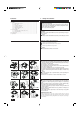
2. Operation Operating range A ON/OFF – CENTRALLY CONTROLLED SWING ˚F DRY COOL TIMER OFF TIMER CLOCK AUTO AUTO FAN AUTO FAN CHECK SET TEMP. START STOP SPEED HEAT STAND BY DEFROST ˚F MODE TIMER ON/OFF CLOCK/TIMER CHECK MODE TEST RUN FAN SPEED AIR DISCHARGE AIR SWEEP SET TEMP.
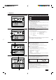
2. Operation A B C D E 2.5. Adjusting airflow direction The vertical air vane helps select the vertical direction of the airflow. (Except PC24, 30, 36, 42EK) 1 Press AIR DISCHARGE button to select the vertical airflow direction. • Each time you press the button, the option changes are displayed on the remote controller, as shown below.
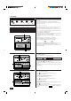
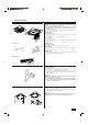
3. Care and cleaning ■ PLH/PL Series B A C Caution: • Always turn off the power, first on the remote controller and then the main switch, before cleaning or servicing the unit. • When installing or removing the filter or the intake grille, do not stand on an unsteady surface. You may fall and injure yourself. Be also careful not to let dust fall into your eyes. Dirty or clogged filters block the airflow and reduce efficiency. Very dirty filters can damage the air-conditioner itself.
3. Care and cleaning 4. Troubleshooting 3.2. Care and cleaning A Clean the filter When the A “FILTER” indicator blinks on the remote controller to alert you to the necessity of cleaning of the filter. ∗ As a guideline for typical office environment, the long-life filter must be cleaned every 2,500 (PL(H))/100 (PC(H), PK(H)) operating hours. ON/OFF – CENTRALLY CONTROLLED SWING DRY COOL TIMER OFF TIMER CLOCK AUTO AUTO FAN AUTO FAN CHECK SET TEMP.
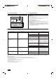
5. Specifications Item Models Cooling *1 BTU/h Capacity Heating *1,*3 BTU/h Heating *2,*3 BTU/h Cooling *1 kW Power Heating *1,*3 kW consumption Heating *2,*3 kW SEER HSPF INDOOR UNIT MODELS External finish Power supply V, Phase, Hz Max. fuse size (time delay) A Min. ampacity A Fan motor F. L. A. Auxiliary heater A (kW) Airflow Dry CFM Lo-Hi Wet CFM W in Dimensions D in H in W in Dimensions D in (GRILLE) H in Weight lbs Weight (GRILLE) lbs OUTDOOR UNIT MODELS External finish Power supply V, Phase, Hz Max.
5. Specifications Item Models Cooling capacity *1 BTU/h Power consumption *1 kW SEER INDOOR UNIT MODELS External finish External finish (GRILLE) Power supply V, Phase, Hz Max. fuse size (time delay) A Min. ampacity A Fan motor F. L. A. Airflow Dry CFM Lo-Hi Wet CFM W in Dimensions D in H in W in Dimensions D in (GRILLE) H in Weight lbs Weight (GRILLE) lbs OUTDOOR UNIT MODELS External finish Power supply V, Phase, Hz Max. fuse size (time delay) A Min. ampacity A Fan motor F. L. A. Model Compressor R. L. A.
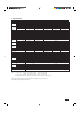
5. Specifications Item Models Cooling *1 BTU/h Capacity Heating *1,*3 BTU/h Heating *2,*3 BTU/h Cooling *1 kW Power Heating *1,*3 kW consumption Heating *2,*3 kW SEER HSPF INDOOR UNIT MODELS External finish Power supply V, Phase, Hz Max. fuse size (time delay) A Min. ampacity A Fan motor F. L. A. Auxiliary heater A (kW) Airflow Dry CFM Lo-Hi Wet CFM W in Dimensions D in H in Weight lbs OUTDOOR UNIT MODELS External finish Power supply V, Phase, Hz Max. fuse size (time delay) A Min. ampacity A Fan motor F.
5. Specifications Item Models Cooling capacity *1 BTU/h Power consumption *1 kW SEER INDOOR UNIT MODELS External finish Power supply V, Phase, Hz Max. fuse size (time delay) A Min. ampacity A Fan motor F. L. A. Airflow Dry CFM Lo-Hi Wet CFM W in Dimensions D in H in Weight lbs OUTDOOR UNIT MODELS External finish Power supply V, Phase, Hz Max. fuse size (time delay) A Min. ampacity A Fan motor F. L. A. Model Compressor R. L. A. L. R. A.
5. Specifications Item Models Cooling *1 BTU/h Capacity Heating *1,*3 BTU/h Heating *2,*3 BTU/h Cooling *1 kW Power Heating *1,*3 kW consumption Heating *2,*3 kW SEER HSPF INDOOR UNIT MODELS External finish Power supply V, Phase, Hz Max. fuse size (time delay) A Min. ampacity A Fan motor F. L. A. Auxiliary heater A (kW) Airflow Dry CFM Lo-Hi Wet CFM W in Dimensions D in H in Weight lbs OUTDOOR UNIT MODELS External finish Power supply V, Phase, Hz Max. fuse size (time delay) A Min. ampacity A Fan motor F.
5. Specifications Models Item Cooling capacity *1 BTU/h Power consumption *1 kW SEER INDOOR UNIT MODELS External finish Power supply V, Phase, Hz Max. fuse size (time delay) A Min. ampacity A Fan motor F. L. A. Airflow Dry CFM Lo-Hi Wet CFM W in Dimensions D in H in Weight lbs OUTDOOR UNIT MODELS External finish Power supply V, Phase, Hz Max. fuse size (time delay) A Min. ampacity A Fan motor F. L. A. Model Compressor R. L. A. L. R. A.