
Service manual


30
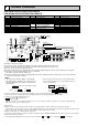
WIRING DIAGRAM
5
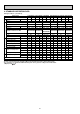
PCH-2GKA-E/PCH-2.5GKA-E/PCH-3GKA-E
PCH-4GKSA-E/PCH-5GKSA-E/PCH-6GKSA-E
240V
230V
220V
230V
220V
YELLOW
ORANGE
RED
1
ON
OFF
234
ON
OFF
[Emergency operation procedure]
(1) Turn on the outdoor unit side circuit breaker, then indoor unit side circuit breaker in this order.
(2) During emergency operation indoor fan runs at high speed but automatic vane remains stop.
(3) If vane closed, open the vane by hand slowly.
(4) Thermostat will not function. Cold air blows out for defrosting during heating thus do not operate defrosting for a long time.
(5) Emergency cooling should be limited to 10 hours maximum.
(The indoor unit heat exchanger may freeze).
(6) If the microcomputer doctor detects the abnormality of the drain-up machine during cooling mode, do not execute emergency
operation.(If causes drain overflow)
NOTES :
1. Since the indoor fan motor (MF) is connected with
230~240V power. If 220V power is used. Change the
dip switch (SW<I.B>)on the indoor controller board
showing fig:
w1.
2. Since the indoor transformer (T)is connected with 240V
power. If 220.230V power is used. Change the wiring con-
nection showing fig:w2.
3. Since the outdoor side electric wiring may change be sure to check the outdoor unit electric wiring for servicing.
4. Indoor and outdoor connecting wires are made with polarities. make wiring matching terminal numbers.
5. Symbols used in wiring diagram above are.
: Connector,
//
: Terminal block.
6. Emergency operation
If remote controller or microcomputer fails but there is no other trouble. emergency operation is possible by setting dip switch
(SW3<I.B>) on the indoor controller board.
[Check items]
(1)Make sure that no other trouble exist the outdoor unit. Trouble with the outdoor unit prevents emergency operation.
(If any trouble exists the outdoor unit error code “P8”will be displayed on the remote controller and the trouble position will be shown
on the outdoor controller LED. See electric wiring diagram of the outdoor unit for details.)
(2)Make sure that there is no trouble with the indoor fan.
Emergency operation will be continuous operation mode due to power ON/OFF (ON/OFF with the remote controller is not possible).
[Emergency operation procedure]
(1)Set the dip switch (SW3<I.B>) on the indoor controller board to on and off for cooling and - on for heating.
2121
fig:w1
Indoor fan motor (MF) for 220V
fig:w2
When power supply is
31
DS(OPTION)
DRAIN
CN50
54
3
2
1
BLK
GRY
(OPTION)
DP
6
D.U.M
CNP
13
6GK5GK4GK
1234
OFF
ON
1234
OFF
ONON
OFF
1234
SW7
MODELS
3GK
1234
OFF
ON
1234
OFF
ON
2.5GK2GK
ON
OFF
1234
SW7
MODELS
3
OFF
ON
1234
TRANSMISSION WIRES
DC12V
14.3VAC
10VAC
13
TRANS
CNT
YLW
WHT
240V
230V
220V
YLW
T
RED
ORN
LED1 12V
POWER
VANE
6
CN6V
1
LED2 5V
POWER
5
1234
REMOCON
POWER
CN40
REMOTE CONTROLLER
INDOOR UNIT
OUTDOOR UNIT
TB5
12
12
BLK
BLK
RT2
ORN
BRN
GRN/YLW
L
N
TB2
POWER SUPPLY
~
(1 PHASE)
AC220-240V 50Hz
X4
MF
2
1
BLU
BLU
12
CN22
TO
REMOCON
SW17
SW18
OFF
ON
4321
R.B
CN2
312
54 12
ON
OFF
87654321
CN1
B.2A.1
TB6
2
3
TO OUTDOOR UNIT
CONNECTING WIRES
DC12V
1
TB4
YLW
OUTDOOR
CN30
123
RT1
LOSSNAY
CN2L
CN20
PIPE
CN21
12
CN51
CENTRALLY
CONTROL
1234
HEATER
CN24
DRAIN
CN50
INTAKE
SW3SW7
12
456 97108
J1
42
J9
SW6
1234
2
J5
SW2
ON
OFF
123456
X4
135
C
WHT
BLK
RED
I.B
FAN1
ZNR
F2 F1
MV
432
1
1
3
POWER
TRANS
CND
CN4T
6
BRN
BRN
RED
RED
BLU
RED
C
CN1<R.B>
CN2<R.B>
CN2L<I.B>
CNP<I.B>
CN50<I.B>
CN51<I.B>
F1,2<I.B>
I.B
J1<I.B>
J5<I.B>
J9<I.B>
FAN MOTOR CAPACITOR
PROGRAM TIMER CONNECTOR
REMOTE SWITCH CONNECTOR
LOSSNAY CONNECTOR
DRAIN-UP MACHINE CONNECTOR
DRAIN SENSOR CONNECTOR
CENTRALLY CONTROL CONNECTOR
FUSE (6.3A 250V)
INDOOR CONTROLLER BOARD
FUNCTION SELECTOR JUMPER RESISTORS
MODEL SELECTOR JUMPER RESISTORS
MODEL SELECTOR JUMPER RESISTORS
LED1<I.B>
LED2<I.B>
MF
MV
R.B
RT1
RT2
SW2<I.B>
SW3<I.B>
SW6<I.B>
DC 12V POWER LED
DC 5V POWER LED
FAN MOTOR
VANE MOTOR
REMOTE CONTROLLER BOARD
ROOM TEMPERATURE THERMISTOR
(0:/15k", 25:/5.4k" DETECT)
INDOOR COIL THERMISTOR
(0:/15k", 25:/5.4k" DETECT)
ADDRESS SELECTOR
EMERGENCY OPERATION SWITCH
MODEL SELECTOR
SW7<I.B>
SW17<R.B>
SW17<R.B>
T
TB2
TB4
TB5
TB6
X4<I.B>
ZNR
DP
DS
MODEL SELECTOR
ADDRESS SELECTOR
FUNCTION SELECTOR
TRANSFORMER
TERMINAL BLOCK (POWER SUPPLY)
TERMINAL BLOCK (INDOOR / OUTDOOR CONNECTING WIRE)
TERMINAL BLOCK (REMOTE CONTROLLER)
LINE TRANSMISSION
TERMINAL BLOCK
FAN MOTOR RELAY
VARISTOR
OPTION DRAIN-UP MACHINE
OPTION DRAIN-UP SENSOR
SYMBOL NAME SYMBOL NAME SYMBOL NAME
SW7
1
234