
Service manual

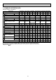


28
1535
680
254
Air intake
1524
270
207
81 96
1620
Air outlet
1547(suspension bolt pitch)
140
150
320 80
18
70
6
87
182
198
245
16
217
(3/8F liquid)
(3/4F gas)
(Drainage)
3
2
8
5
1
4
Electrical box
When electrical
box is pulled
down
[ Front view ]
Celling
93
160
38
38 140
42 239
6~7
525
1545
687
263
171
138
86
192
236
1
45
7
2
Electrical box
70
229
PCH-5GKSA-E
PCH-6GKSA-E
1 Unit drain pipe (26mm I.D.) 5 Refrigerant-pipe connection (liquid pipe side/flared connection)
2 Unit drain pipe (for the left arrangement) 6 Knock out hole for upper drain pipe arrangement
3 Knock out hole for left drain-piping arrangement 7 Knock out hole for left drain pipe arrangement
4 Refrigerant-pipe connection (gas pipe side/flared connection) 8 Knock out hole for wiring arrangement
NOTES:
1. Use M10 or W3/8 screws for anchor bolt.
2. Please be sure when installing the drain-up machine (option parts).
refrigerant pipe will be only upper drain pipe arrangement.