
Service manual


25
4
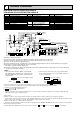
1. INDOOR UNIT
PCH-2GKA-E
180
210
157
15
85
182 (3/8F) liquid
201 (5/8F) gas
241 (Drainage)
Air intake
918
254
680
Electrical box
226
70
525
928
352
263
171
138
86
175
131
38
79
38
161
32
179
42
6~7
Celling
Electrical box
[Front view]
When electrical
box is pulled
down
3
2
8
5
1
4
6
2
7
17
150
140
70
320
80
933 (suspension bolt pitch)
983
1000
Air outlet
81
904
76
46
1 Unit drain pipe (26mm I.D.) 5 Refrigerant-pipe connection (liquid pipe side/flared connection)
2 Unit drain pipe (for the left arrangement) 6 Knock out hole for upper drain pipe arrangement
3 Knock out hole for left drain-piping arrangement 7 Knock out hole for left drain pipe arrangement
4 Refrigerant-pipe connection (gas pipe side/flared connection) 8 Knock out hole for wiring arrangement
NOTES:
1. Use M10 or W3/8 screws for anchor bolt.
2. Please be sure when installing the drain-up machine (option parts).
refrigerant pipe will be only upper drain pipe arrangement.
OUTLINES AND DIMENSIONS