999 SPLIT-TYPE,HEAT PUMP AIR CONDITIONERS No. OC191 TECHNICAL & SERVICE MANUAL Series PCH Indoor unit [Models names] [Service Ref.] PCH-2GKA-E PCH-2.5GKA-E PCH-3GKA-E PCH-4GKSA-E PCH-5GKSA-E PCH-6GKSA-E PCH-2GKA PCH-2.5GKA PCH-3GKA PCH-4GKSA PCH-5GKSA PCH-6GKSA This manual does not cover the following outdoor units. When serving them, please refer to the service manual No.OC150 and this manual in a set. [Service Ref.] PUH-2VKA2.UK PUH-2.5VKA2.UK PUH-3VKA2.UK PUH-3YKA2.UK PUH-4YKSA2.UK PUH-5YKSA2.
1 PART NAMES AND FUNCTION ● Indoor (Main) Unit Left/right guide vanes Change the direction of airflow from the horizontal blower. Air outlet Long-life filter Removes dust and foreign matter from air coming in through the grille (Recommended cleaning interval : Approx, every 2,500 operating hours) Air intake Up/down guide vanes Change the direction of airflow from the vertical blower.
● Display CENTRALLY CONTROLLED display This indicates when the unit is controlled by optional features such as central control type remote controller. display The current time , start time and stop time can be displayed in ten second intervals by pressing the time switch button. The start time or stop time is always displayed during the timer operation. display display This displays the air direction. This indicates when the continuous operation and time operation modes are set.
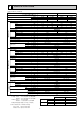
2 SPECIFICATIONS Rating Conditions (JIS B8616) Service Ref. Item PCH-2GKA-E Cooling Heating Cooling Heating 18,400 21,200 23,900 24,200 5,400 6,200 7,000 7,100 2.30 2.32 2.59 2.36 PCH-2GKA-E PCH-2.5GKA-E Single phase. 50Hz. 220-240V 0.10 0.10 0.13 0.13 0.43 0.43 0.55 0.55 1.20 1.20 1.27 1.27 Munsell 0.70Y 8.59 / 0.97 Plate fin coil Sirocco (direct))2 Sirocco (direct))3 0.054 0.
Rating Conditions (JIS B8616) Service Ref. Item Function INDOOR UNIT Total input Service Ref. Power supply Input Running current Starting current External finish Heat exchanger Fan Fan(drive))No. Fan motor output Airflow(Low-High) External static pressure Booster heater Operation control & Thermostat Noise level(Low-High) Unit drain pipe I.D. OUTDOOR UNIT REFRIGERANT PIPING W D H Weight Service Ref.
Rating Conditions (JIS B8616) Service Ref. Item Function Btu/h W kW Capacity Total input Service Ref. Power supply Input Running current Starting current External finish Heat exchanger Fan Fan(drive))No. Fan motor output Airflow(Low-High) External static pressure Booster heater Operation control & Thermostat Noise level(Low-High) Unit drain pipe I.D. INDOOR UNIT kW A A OUTDOOR UNIT Dimensions W D H Weight Service Ref.
3 DATA 1. PERFORMANCE DATA 1) COOLING CAPACITY<1> PCH-2GKA Indoor Indoor Intake air Intake air °C DB °C WB CA 20 SHC(W) SHF P.C. Outdoor intake air °C DB 25 CA SHC(W) SHF P.C. CA 30 SHC(W) SHF P.C. 20 16 5448 3160 0.58 1.84 5299 3073 0.58 1.92 5104 2960 0.58 2.07 20 18 5800 2668 0.46 1.88 5648 2598 0.46 1.96 5442 2503 0.46 2.12 20 20 6157 2093 0.34 1.92 6012 2044 0.34 2.00 5798 1971 0.34 2.16 22 16 5448 3596 0.66 1.84 5299 3497 0.66 1.
COOLING CAPACITY<2> PCH-2GKA Indoor Indoor Intake air Intake air °C DB °C WB CA 35 SHC(W) SHF P.C. Outdoor intake air °C DB 40 CA SHC(W) SHF P.C. CA 45 SHC(W) SHF P.C. 20 16 4897 2840 0.58 2.22 4678 2713 0.58 2.37 4447 2579 0.58 2.52 20 18 5226 2404 0.46 2.27 5000 2300 0.46 2.43 4764 2191 0.46 2.58 20 20 5574 1895 0.34 2.33 5341 1816 0.34 2.49 5099 1734 0.34 2.66 22 16 4897 3232 0.66 2.22 4678 3088 0.66 2.37 4447 2935 0.66 2.
COOLING CAPACITY<3> PCH-2.5GKA Indoor Indoor Intake air Intake air °C DB °C WB CA 20 SHC(W) SHF P.C. Outdoor intake air °C DB 25 CA SHC(W) SHF P.C. CA 30 SHC(W) SHF P.C. 20 16 7062 4167 0.59 2.08 6869 4052 0.59 2.16 6616 3904 0.59 2.33 20 18 7519 3534 0.47 2.12 7321 3441 0.47 2.21 7054 3316 0.47 2.38 20 20 7981 2793 0.35 2.16 7794 2728 0.35 2.25 7515 2630 0.35 2.44 22 16 7062 4713 0.67 2.08 6869 4602 0.67 2.16 6616 4433 0.67 2.
COOLING CAPACITY<4> PCH-2.5GKA Indoor Indoor Intake air Intake air °C DB °C WB CA 35 SHC(W) SHF P.C. Outdoor intake air °C DB 40 CA SHC(W) SHF P.C. CA 45 SHC(W) SHF P.C. 20 16 6348 3745 0.59 2.50 6064 3578 0.59 2.67 5765 3401 0.59 2.84 20 18 6775 3184 0.47 2.56 6482 3046 0.47 2.73 6176 2902 0.47 2.91 20 20 7225 2529 0.35 2.62 6923 2423 0.35 2.81 6609 2313 0.35 3.00 22 16 6348 4253 0.67 2.50 6064 4063 0.67 2.67 5765 2863 0.67 2.
COOLING CAPACITY<5> PCH-3GKA Indoor Indoor Intake air Intake air °C DB °C WB CA 20 SHC(W) SHF P.C. Outdoor intake air °C DB 25 CA SHC(W) SHF P.C. CA 30 SHC(W) SHF P.C. 20 16 7566 4237 0.56 2.63 7359 4121 0.56 2.74 7089 3970 0.56 2.95 20 18 8056 3545 0.44 2.68 7844 3451 0.44 2.80 7558 3326 0.44 3.02 20 20 8551 2736 0.32 2.73 8350 2672 0.32 2.85 8052 2577 0.32 3.08 22 16 7566 4842 0.64 2.63 7359 4710 0.64 2.74 7089 4537 0.64 2.
COOLING CAPACITY<6> PCH-3GKA Indoor Indoor Intake air Intake air °C DB °C WB CA 35 SHC(W) SHF P.C. Outdoor intake air °C DB 40 CA SHC(W) SHF P.C. CA 45 SHC(W) SHF P.C. 20 16 6802 3809 0.56 3.16 6498 3639 0.56 3.38 6177 3459 0.56 3.59 20 18 7259 3194 0.44 3.24 6945 3056 0.44 3.46 6617 2911 0.44 3.69 20 20 7741 2477 0.32 3.32 7418 2374 0.32 3.56 7081 2266 0.32 3.80 22 16 6802 4353 0.64 3.16 6498 4158 0.64 3.38 6177 3953 0.64 3.
COOLING CAPACITY<7> PCH-4GKSA Indoor Indoor Intake air Intake air °C DB °C WB CA 20 SHC(W) SHF P.C. Outdoor intake air °C DB 25 CA SHC(W) SHF P.C. CA 30 SHC(W) SHF P.C. 20 16 10088 5851 0.58 2.69 9812 5691 0.58 2.81 9452 5482 0.58 3.02 20 18 10741 4941 0.46 2.75 10459 4811 0.46 2.87 10078 4636 0.46 3.09 20 20 11402 3877 0.34 2.80 11134 3785 0.34 2.92 10736 3650 0.34 3.16 22 16 10088 6658 0.66 2.69 9812 6476 0.66 2.81 9452 6238 0.66 3.
COOLING CAPACITY<8> PCH-4GKSA Indoor Indoor Intake air Intake air °C DB °C WB CA 35 SHC(W) SHF P.C. Outdoor intake air °C DB 40 CA SHC(W) SHF P.C. CA 45 SHC(W) SHF P.C. 20 16 9069 5260 0.58 3.24 8663 5025 0.58 3.46 8236 4777 0.58 3.68 20 18 9678 4452 0.46 3.32 9260 4259 0.46 3.55 8822 4058 0.46 3.78 20 20 10322 3509 0.34 3.40 9890 3363 0.34 3.64 9442 3210 0.34 3.89 22 16 9069 5985 0.66 3.24 8663 5718 0.66 3.46 8236 5436 0.66 3.
COOLING CAPACITY<9> PCH-5GKSA Indoor Indoor Intake air Intake air °C DB °C WB CA 20 SHC(W) SHF P.C. Outdoor intake air °C DB 25 CA SHC(W) SHF P.C. CA 30 SHC(W) SHF P.C. 20 16 12510 7881 0.63 3.57 12167 7665 0.63 3.72 11720 7384 0.63 4.00 20 18 13319 6793 0.51 3.64 12969 6614 0.51 3.79 12496 6373 0.51 4.10 20 20 14138 5514 0.39 3.71 13806 5384 0.39 3.87 13313 5192 0.39 4.19 22 16 12510 8882 0.71 3.57 12167 8639 0.71 3.72 11720 8321 0.71 4.
COOLING CAPACITY<10> PCH-5GKSA Indoor Indoor Intake air Intake air °C DB °C WB CA 35 SHC(W) SHF P.C. Outdoor intake air °C DB 40 CA SHC(W) SHF P.C. CA 45 SHC(W) SHF P.C. 20 16 11245 7085 0.63 4.29 10743 6768 0.63 4.58 10212 6434 0.63 4.87 20 18 12001 6120 0.51 4.40 11482 5856 0.51 4.70 10939 5579 0.51 5.00 20 20 12799 4992 0.39 4.50 12264 4783 0.39 4.82 11708 4566 0.39 5.15 22 16 11245 7984 0.71 4.29 10743 7627 0.71 4.58 10212 7251 0.71 4.
COOLING CAPACITY<11> PCH-6GKSA Indoor Indoor Intake air Intake air °C DB °C WB CA 20 SHC(W) SHF P.C. Outdoor intake air °C DB 25 CA SHC(W) SHF P.C. CA 30 SHC(W) SHF P.C. 20 16 14628 8046 0.55 3.98 14228 7825 0.55 4.15 13705 7538 0.55 4.47 20 18 15575 6697 0.43 4.06 15165 6521 0.43 4.24 14613 6283 0.43 4.57 20 20 16532 5125 0.31 4.14 16144 5005 0.31 4.32 15568 4826 0.31 4.67 22 16 14628 9216 0.63 3.98 14228 8963 0.63 4.15 13705 8634 0.63 4.
COOLING CAPACITY<12> PCH-6GKSA Indoor Indoor Intake air Intake air °C DB °C WB CA 35 SHC(W) SHF P.C. Outdoor intake air °C DB 40 CA SHC(W) SHF P.C. CA 45 SHC(W) SHF P.C. 20 16 13150 7232 0.55 4.79 12562 6909 0.55 5.12 11942 6568 0.55 5.44 20 18 14033 6034 0.43 4.91 13426 5773 0.43 5.25 12792 5501 0.43 5.58 20 20 14967 4640 0.31 5.03 14341 4446 0.31 5.39 13691 4244 0.31 5.75 22 16 13150 8284 0.63 4.79 12562 7914 0.63 5.12 11942 7523 0.63 5.
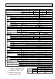
Cooling capacity correction factors Service Ref. PCH-2GKA-E PCH-2.5GKA-E PCH-3GKA-E PCH-4GKSA-E PCH-5GKSA-E PCH-6GKSA-E 5m 1.00 1.00 1.00 1.00 1.00 1.00 10m 0.992 0.989 0.981 0.989 0.981 0.975 15m 0.983 0.980 0.968 0.980 0.968 0.955 Refrigerant piping length (one way) 20m 25m 30m 35m 0.978 0.966 0.959 0.950 0.970 0.960 0.950 0.940 0.952 0.940 0.925 0.913 0.970 0.960 0.950 0.940 0.952 0.940 0.925 0.913 0.935 0.918 0.900 0.884 40m 0.945 0.930 0.900 0.930 0.900 0.869 45m — 0.920 0.886 0.920 0.886 0.
3. ELECTRICAL DATA Outdoor Indoor Rating Conditions (JIS B8616) Cooling : Indoor 27:DB. 19:WB. Outdoor 35:DB. Heating : Indoor 20:DB. Outdoor 7:DB. 6:WB. Indoor……220V 50Hz 1phase Refrigerant piping length : 5m Outdoor… 220V 50Hz 1phase / 380V 50Hz 3phase PCH-2GKA-E PCH-2.5GKA-E PCH-3GKA-E PCH-4GKSA-E PCH-5GKSA-E PCH-6GKSA-E Service Ref.
4. STANDARD OPERATION DATA Rating Conditions (JIS B8616) Total V A Outdoor Indoor side Refrigerant circuit side W kW Electrical circuit Service Ref. Mode Capacity Input Indoor unit Service Ref. Phase, Hz Volts Amperes Outdoor unit Service Ref. Phase, Hz Volts Amperes Discharge pressure Suction pressure Discharge temperature Condensing temperature Suction temperature Ref.
SPL(db(A)) Hi 42 Lo 37 PCH-2.5GKA PCH-3GKA LINE 90 90 80 80 70 NC-70 60 NC-60 50 NC-50 40 NC-40 30 NC-30 20 APPROTIMATE TERESHOLD OF REARING FOR CONTINUOUS NOISE OCTAVE BAND SOUND PRESSURE LEVEL, dB re 0.002 MICRO BAR OCTAVE BAND SOUND PRESSURE LEVEL, dB re 0.002 MICRO BAR 5.
PCH-6GKSA NOTCH SPL(db(A)) Hi 48 Lo 42 LINE OCTAVE BAND SOUND PRESSURE LEVEL, dB re 0.002 MICRO BAR 90 80 70 NC-70 60 NC-60 50 NC-50 40 NC-40 30 NC-30 20 APPROTIMATE TERESHOLD OF REARING FOR CONTINUOUS NOISE NC-20 10 63 125 250 500 1000 2000 4000 8000 BAND CENTER FREQUENCIES, Hz Ambient temperature 27˚C ceiling 1m 1m about 1.
When electrical box is pulled down 6~7 2 928 7 Electrical box 70 525 Celling 8 226 86 2 138 171 263 352 5 1 4 Air intake Air outlet 918 1000 904 983 933 (suspension bolt pitch) 140 6 70 15 85 (3/8F) liquid (5/8F) gas (Drainage) 182 201 241 NOTES: 1. Use M10 or W3/8 screws for anchor bolt. 2. Please be sure when installing the drain-up machine (option parts). refrigerant pipe will be only upper drain pipe arrangement.
When electrical box is pulled down 2 1235 7 Electrical box 525 Celling 70 8 226 2 86 138 171 263 416 5 1 4 Air outlet Air intake 131 [ Front view ] 46 175 1 Electrical box 32 161 3 179 42 38 79 38 1228 1310 1214 1290 1240 (suspension bolt pitch) 150 6~7 140 70 6 15 85 (3/8F liquid) (5/8F gas) (Drainage) 182 201 241 NOTES: 1. Use M10 or W3/8 screws for anchor bolt. 2. Please be sure when installing the drain-up machine (option parts).
3 239 2 When electrical box is pulled down 42 93 7 Electrical box 525 160 70 229 1235 Celling [ Front view ] 8 2 687 86 138 171 263 5 192 4 Air intake Air outlet 1 1228 1310 1214 1240 (suspension bolt pitch) 140 70 6 270 6~7 16 87 (3/8F liquid) (3/4F-gas) (Drainage) 182 198 245 Refrigerant-pipe connection (liquid pipe side/flared connection) Knock out hole for upper drain pipe arrangement Knock out hole for left drain pipe arrangement NOTES: Knock out hole for wiring arra
239 42 When electrical box is pulled down Electrical box 93 6~7 7 Electrical box 525 160 229 1545 70 Celling [ Front view ] 2 8 38 140 687 38 86 138 171 263 5 1 4 Air outlet Air intake 192 1535 1620 1524 1547(suspension bolt pitch) 18 140 70 6 16 87 (3/8F liquid) (3/4F gas) (Drainage) 182 198 245 NOTES: 1. Use M10 or W3/8 screws for anchor bolt. 2. Please be sure when installing the drain-up machine (option parts).
2. REMOTE CONTROLLER Unit : mm FILTER CHECK MODE TEST RUN TEST RUN 120 FILTER CHECK MODE 18 130 83.5 Rear side wiring arrangement opening.
5 WIRING DIAGRAM PCH-2GKA-E/PCH-2.5GKA-E/PCH-3GKA-E PCH-4GKSA-E/PCH-5GKSA-E/PCH-6GKSA-E SYMBOL C CN1 CN2 CN2L CNP CN50 CN51 F1,2 I.B J1 J5 J9 NAME FAN MOTOR CAPACITOR PROGRAM TIMER CONNECTOR REMOTE SWITCH CONNECTOR LOSSNAY CONNECTOR DRAIN-UP MACHINE CONNECTOR DRAIN SENSOR CONNECTOR CENTRALLY CONTROL CONNECTOR FUSE (6.
6 REFRIGERANT SYSTEM DIAGRAM PCH-2GKA-E/PUH-2VKA2.UK Refrigerant flow in cooling Refrigerant flow in heating PCH-2.5GKA-E/PUH-2.5VKA2.UK PCH-3GKA-E/PUH-3VKA2.UK,PUH-3YKA2.UK Oil separator Refrigerant pipe 4-way valve (option) 15.
7 OPERATION FLOW-CHART MAIN OPERATION START Power circuit breaker 1 NO YES YES Check SW ON twice NO Operation SW ON w1 YES NO “OFF” timer YES NO NO Set time complete “ON” timer NO YES YES YES Set time complete w2 NO NO Trouble Remote controller operation display YES STOP Trouble STOP PROTECTION DEVICE SELF HOLD RELEASE PROTECTION DEVICE SELF HOLD Operating mode (COOL) NO Operating mode (DRY) w3 Remote controller indicator lamp OFF Remote controller trouble display NO Operating mo
COOLING OPERATION COOL operation Four-way valve/OFF NO Initial COOLING w8 YES Vane initial setting Vane 40 deg downward angle 60 deg downward angle NO YES Fan speed LOW NO YES NO Vane setting notch Downward discharge 1 hour YES Vane horizontal airflow w9 NO Compressor YES thermostat ON NO Allowance cancel NO YES 3-minute time delay NO 6-minute time delay YES NO NO 3-minute compressor operation w10 YES Coil frost prevention YES Allowance period NO 6 minute time delay Allowance set Coil frost
HEATING OPERATION A Heat operation w11 YES Heating area w15 Initial HEATING YES NO Vane setting notch NO Defrost release NO Defrost 30 min. elapse 2 YES Vane initial setting NO YES Defrosting NO PCH-GKH(S)A Type NO 3-minute NO Auxiliary heater OFF NO NO Indoor coil thermistor is 60°C or higher Outdoor unit trouble NO Four-way valve ON FAN speed NO is Low YES 1 Hor adjust YES in process NO YES Compressor ON Airflow 10% up NO YES Compressor thermostat ON w9 3 min.
DRY OPERATION DRY operation Four-way valve / OFF NO Initial dry operation w8 YES Vane setting notch Vane initial setting YES w12 Room temperature is 18°C or lower NO NO During compressor ON YES 3-minute compressor operation NO NO YES NO YES 3-minute time delay w9 Compressor & thermostat ON YES Compressor & thermostat ON w9 NO YES NO Compressor ON time completes 10-minute compressor OFF NO YES YES w13 10-minute compressor OFF timer start Compressor ON time set Compressor OFF C
8 MICROPROCESSOR CONTROL 1.OUTLINE OF MICROPROCESSOR CONTROL INPUT to remote controller ● OFF-ON switching. ● COOL/DRY-AUTO-HEAT selector switching. ● Thermostat setting. ● TIMER mode selector-switching and Timer setting. ● HIGH-LOW fan speed switching. ● AUTO Vane selector (AIR DISCHARGE) switching. ● TEST RUN switching. ● CHECK mode switching. (Self diagnostic trouble shooting) Remote controller board ● Processes and transmits orders.
2. INDOOR UNIT CONTROL 2-1COOL operation 1 Press POWER ON/OFF button. 2 Press the a button to display “f”. 3 Press the i TEMP. button to set the desired temperature. NOTE: Set temperature changes 1°C when the or button is pressed one time. Cooling 19°C to 30°C FILTER CHECK MODE TEST RUN 4 Operation starts by POWER button ON. Room temperature becomes equal to set temperature. Room temperature rises above set temperature. Operation stops by POWER button OFF.
5 Coil frost protection When indoor coil temperature becomes -15°C or below,coil frost protection will proceed as follows. After the compressor has been continuously operated for 3 minutes or more,and the indoor coil temperature has been -15°C or below for 3 minutes,the coil frost protection will start. Compressor stops for 6 minutes,and then restarts.
(3) Auto vane control Auto vane position is set to horizontal airflow at the start-up of COOL operation. It can then be changed by the remote controller. (a) Stop mode (fixed operation) ( i ) At start-up of COOL operation, the auto vane is set to horizontal airflow direction. ( ii ) Discharge direction can be changed with button. 1 Fan speed : LOW Horizontal 40° 60° SWING 40° 60° SWING 2 Fan speed : HIGH Horizontal 20° w Vane angle can be change to upper angle by cutting off the J5-3.
(a) The auto vane is driven by DC12V motor. (b) Airflow direction is selected depends on the number of pulse were sent. (c) Before start driving the auto vane, detect the standard position first, output the number of pulse to each airflow. (d) The speed of the auto vane drive for both open and close are set at 200 pulse/sec. (e) Method of driving the auto vane.
2-2 DRY operation 1 Press POWER ON/OFF button. 2 Press the a button to display “ e ”. 3 Press the i TEMP. button to set the desired temperature. NOTE: The set temperature changes 1°C when the button is pressed one time. Dry 19°C to 30°C. FILTER CHECK MODE TEST RUN 4 Operation starts by POWER button ON. Room temperature becomes equal to set temperature. Room temperature rises above set temperature. Operation stops by POWER button OFF.
4The compressor will not start when the room temperature is below 18:. The compressor start intermittent operation when the power is turned ON with room temperature above 18:. The compressor ON/OFF time depends on the thermostat ON/OFF and the following room temperature. After 3-minute compressor operation. ● If the room temperature thermistor reads above 28: with thermostat ON, the compressor will operate for 6 more minutes and then stop for 3 minutes.
2-3 HEAT operation 1 Press POWER ON/OFF button. 2 Press the a button to display “ g ”. 3 Press the i TEMP. button to set the desired temperature. NOTE: The set temperature changes 1°C when the or button is pressed one time. Heating 17°C to 28°C [DEFROST] The [DEFROST] symbol is only displayed during the defrost operation. [STANDBY] The [STANDBY] symbol is displayed from the heating operation starts until the heated air begins to blow.
(1) Compressor control 1 3-minute time delay To prevent overload, the compressor will not start within 3 minutes after stop. 2 The compressor runs when the room temperature is higher than the set temperature. The compressor stops when the room temperature is equal to or lower than the set temperature. 3 The compressor stops in check mode or during protective functions. 4 Overheat protection. When the indoor coil thermistor reads 70: or above, the overheat protection will start.
(3) Auto vane control (a) STOP mode (fixed operation) ( i ) The airflow direction at the start-up of HEAT operation is the same as that of the previous operation. ( ii ) The airflow direction can be charged by the remote controller setting. horizontal 20° 40° 60° SWING In the following cases, airflow direction becomes horizontal regardless of the remote controller setting.
(5) Indoor coil thermistor abnormality detection An abnormality can be detected during compressor ON, except for the following. ● For the first 30 minutes after the temperature difference between the indoor coil temperature and room temperature enters the RANGE C. ● When the temperature difference enters the RANGE C until it moves to the RANGE B.
2-4 AUTO operation (Automatic COOL/HEAT change over operation) 1 Press POWER ON/OFF button. 2 Press the button to display “ ” 3 Press the TEMP. button to set the desired temperature. NOTE: The set temperature changes 1°C when the or button is pressed one time. Automatic 19 to 28°C ●“AUTOMATIC” works to change by itself the operation mode either to cooling or heating according to the room temperature.
2-5 Auto vane control To change the air flow direction, press FILTER CHECK MODE button. NOTE: Vane angle can be change to upper angle by cutting off the J5-3. (Jumper resistance of indoor units) TEST RUN 4 1 Horizontal 2 20˚ 3 40˚ 4 60˚ 5 swing Changes by pressing the Available in COOL operation with fan speed on HIGH or in HEAT operation. Unavailable in DRY operation.
2-6 TIMER operation AUTO STOP ·········The air conditioner stops after the set time lapses. AUTO START ········The air conditioner starts after the set time lapses. TIMER OFF ··········Timer is not active. 1. Press POWER ON/OFF button. FILTER CHECK MODE TEST RUN 2. Press “ ” button to select AUTO STOP or AUTO START. 3. Press “ ” button to set desired time. Time setting is in 1 hour units for up to 24 hours. Each time HOURS button is pressed, set time increases by 1 hour.
(1) Indoor coil temperature code During the test run, the indoor coil temperature code from 1 to 15 is displayed on the remote controller instead of room temperature. The code should fall with the lapse of time in normal COOL operation, and should rise in normal HEAT operation.
2-9 Interlock with ventilation system (LOSSNAY) Mr. SLIM/LOSSNAY interlock operation is available by using the optional parts listed below. (1) System organization Relay box (PZ-12RB-E) Relay box Mr. SLIM LOSSNAY LOSSNAY Power supply Mr. SLIM Power supply Remote controller LOSSNAY control switch (PZ-05SLB2-E) Remote display adapter (PAC-SA88HA-E) Remote controller LOSSNAY control switch (PZ-05SLB2-E) (2) LOSSNAY models connectable to Mr.
2-10 Dip switch functions Each figure shows the initial factory setting. 1) On remote controller board (1) SW17(Address selector) 8 7 6 5 4 3 2 1 OFF ON SW17-1~6) For address setting SW17-7) When two remote controllers are used,this switch sets the controller function. OFF:The remote controller is set as a main controller. ON:The remote controller is set as a sub controller.
(2) SW2 (Address selector) Used insetting the unit-address for group control. 1 2 3 4 5 6 ON OFF (3) SW3 (Emergency operation switch) Normal operation 1 2 ON OFF For emergency cooling 1 2 ON OFF For emergency heating 1 2 ON OFF (4) J5 (Model selector emergency heating) 2 3 4 J5-2) Provided : For models with heat pump. Not provided : For models without heat pump. J5-3) Available : Vane horizontal angle ...... Normal Not available : Vane horizontal angle ......
2-11 INDOOR FAN CONTROL Each figure shows the initial factory setting. (1) Fan motor max. rotational frequency for PCH-GK(S)A-E (2) Indoor fan relay output (a) During fan ON The indoor fan relay turns ON. One second later, the phase control will start. (b) During fan OFF The phase control turns OFF. One second later, the indoor fan relay will turn OFF. Service Ref. PCH-2GKA-E PCH-2.
3. OUTDOOR UNIT CONTROL 3-1 Outdoor fan control The rotational frequency of outdoor fan is phase-controlled according to the outdoor coil temperature. This control allows the cooling operation even with the low outside-air temperature and the heating operation even with the high outside-air temperature. 3-2 Outdoor unit control The outdoor unit turns ON/OFF the cooling/heating operation according to orders given from the indoor unit.
3-5 Defrosting in HEAT mode Defrosting starts. Defrosting stops. Indoor unit Extra LOW → LOW ON Indoor fan OFF Auto vane Horizontal ON OFF Set direction (Remote controller still displays set direction.) Horizontal Set direction Outdoor unit ON 4-way valve OFF Bypass valve ON OFF Outdoor fan ON OFF Compressor ON OFF (1) Start conditions A. When all of the following conditions are satisfied, defrosting will start.
(3) Defrost interval The defrost interval time is determined as follows. ● Initial defrost interval is 50 minutes. ● The defrost interval after defrosting depends on the preceding defrosting time as shown below. Defrosting operation time Next defrost interval 3 minutes or below 120 minutes 3 to 7 minutes 80 minutes 7 to 10 minutes 60 minutes 10 to 15 minutes 40 minutes 15 minutes (Maximum) 30 minutes NOTE1:If the unit stops during defrosting , the next defrost interval will be 50 minutes.
3-7 Service functions (1) Compulsory defrosting 1 When all of the following conditions are satisfied, pressing SW2 starts the compulsory defrosting. ● During HEAT mode ● The compressor is ON. ● The outdoor coil temperature is being displayed by LED. (Outdoor controller board dip switch SW3-1 : OFF, SW3-2 : ON) ● The outdoor coil thermistor reads 8°C or below. 2 The operation state and the termination conditions of the compulsory defrosting are the same as those of the normal defrosting.
9 TROUBLESHOOTING 1.TROUBLES IN TEST RUN Symptom Cause Check points The display “CENTRALLY CONTROLLED” on remote controller dose not disappear. 1) Wrong address setting of remote controller/indoor controller board. 2) Timer adapter is connected to the remote controller. 3) Signal transmission error between indoor unit and remote controller. 1) Check the address setting of remote controller and indoor controller. 2) Make sure the timer adapter is used correctly.
2. SELF DIAGNOSTIC FUNCTION WITH REMOTE CONTROLLER 2-1 When malfunction occurs during operation When a malfunction occurs, the indoor and outdoor units stop and the malfunction is displayed on the LCD of the remote controller. (1) ON the set temperature display part, “CHECK” appears, and the unit CHECK mode address and the check code are displayed alternately at one-second intervals.
Check Diagnosis of malfunction Cause Check points code 1) Check the transmission wire. EO Signal transmitting/receiving During individual unit control 2) Check with another remote controller. If “EO” is 1) Bad contact of transmission error still indicated, replace the indoor controller wire (Indoor controller does not board. respond to remote controller 2) Signal transmitting/receiving cirIf other check code appears. replace the origicuit is abnormal. signal.) nal remote controller.
3. SERVICE DATA INDICATION BY SWITCHES ON OUTDOOR CONTROLLER BOARD Setting dip switches SW2 and SW3 on the outdoor controller board enables LED to show the output state and check code. Output state is shown by LED lighting, and check code by blinking. SW1 : Turning SW1 ON clears the check code. If SW1 is turned ON while the check code is blinking , the indication changes to output state indication. NOTE : SW1 is usually available independent of SW3 setting.
3-1 Outdoor coil temperature To obtain data on the outdoor coil temperature, add the number of bits of lighting LED, and see the graph below to find the temperature. C 100 (Short 238 38 bits) bits) 80 60 Temperature 40 20 0 -20 -40 (Open 8 219 bits) bits) 50 0 100 150 200 255 Number of bits 3-2 Fan output step To obtain data on the fan output step, add the number of bits of lighting LED, and see the graph below to find the fan rotational frequency. 1 PUH-2/4K type 2PUH-2.
4. TROUBLESHOOTING ACCORDING TO CHECK CODE Blinking Diagnosis of malfunction LED LD1 Reversed phase Cause Check point Phases L1, L2, and L3 are con- Check the power supply connection. nected improperly. LD2 Open phase LD3 Outdoor coil thermistor is ● Outdoor coil thermistor is abnormal. (Open circuit or short broken. circuit) ● Thermistor was connected incorrectly. LD4 High pressure switch (63H2) function ● 62H2 was badly connected. ● 63H2 was working. ● Check 63H2 and the outdoor fan motor.
6. WRONG WIRING ON SITE 6-1 Between remote controller and indoor unit If the wire is disconnected between the remote controller and the indoor unit, nothing is displayed on the remote controller when the POWER button is pressed. The beep sound will also not be heard.
7. OTHER TROUBLES AND CAUSES Vanes do not work. Vane motor does not work. Vane motor is damaged. Connector is poorly connected. Vane motor is poorly assembled. Indoor controller board is damaged. Unit stops after 5 to 20 seconds operation Air discharge display is OFF and button does not operate. In this case, remote controller is normal. Refer to check code on remote controller display. See page 64. Protection function is working.
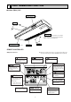
10 DISASSEMBLY PROCEDURE PCH-3GKA-E OPERATING PROCEDURE PHOTOS&ILLUSTRATIONS 1. Removing the air intake grille (1) Slide the intake grille holding knobs (at two locations) backward to open the intake grille. (2) When the intake grille left open, push the stoppers on the rear hinges (at two locations) to pull out the intake grille. Figure 1 Intake grille slide Intake grille Holding knobs Figure 2 Hinges Pull out the intake grill 2. Removing the electrical box (1) Remove the air intake grill.
OPERATING PROCEDURE PHOTOS&ILLUSTRATIONS 3. Removing the fan motor (1) Remove the intake grill. (2) Disconnect the fan motor connector. (3) Unscrew screws for removing the motor guard. (4) Unscrew screws for removing the fan guard. (5) Remove the screw for removing the motor support at both left and right side. (6) Loosen the set screws at the fan motor side of the connecting joint. (7) Slide the fan motor to the left side and pull it out. Photo 2 Motor guard Screws Motor Set screws Motor support 4.
OPERATING PROCEDURE PHOTOS 6. Removing the vane motor (1) Remove the air intake grill. (2) Remove the left side panel. (3) Remove the relay connector of vane motor. (4) Remove the electrical box. (5) Remove the screws of vane motor, then remove vane motor. (Note) Connect the lead wires and connectors properly and place them in the proper position so that the wires are not pinched by other parts. Photo 4 Screw Relay connector of the pipe thermistor Check panel Left side panel Photo 5 Hold 7.
OPERATING PROCEDURE PHOTOS 9. Removing the drain pan (1) Remove the air intake grill. (2) Remove the beam. (3) Remove the side panel (right and left). (4) Remove the under panel. Remove the screws of the right and left side drain pan. (5) Remove the insulation in centre of the drain pan, and after removing the screw, remove the drain pan. Photo 8 (Note) Please aware that there might be drain left in the drain pan when you remove the drain pump (option). Screw 10.
OPERATING PROCEDURE PHOTOS 12. Removing the heat exchanger. (1) Remove the air intake grill. (2) Remove the beam. (3) Remove the side panel (right and left). (4) Disconnect the relay connector. (5) Remove the under panel. (6) Remove the drain pan. (7) Unscrew the screw of the pipe cover, and remove the pipe cover. (8) Unscrew the screw of the pipe support, and remove the pipe support. (9) Unscrew the screw of the heat exchanger, and remove the heat exchanger. Remove the heat exchanger with care.
11 PARTS LIST STRUCTURAL PART PCH-2GKA-E 2 19 13 15 4 12 16 28 10 24 11 5 23 17 14 7 18 8 1 9 6 27 72 3 20 26 25
Part numbers that are circled are not shown in the figure Q'ty / set No. Parts No. Parts Name Specifications PCH-2 Remarks (Drawing No.) GKA-E 1 R01 17J 661 RIGHT SIDE PANEL 1 2 R01 17J 662 LEFT SIDE PANEL 1 3 R01 17J 669 UNDER PANEL 1 4 R01 17J 676 REAR PANEL 1 5 R01 A14 500 L.L. FILTER 1 6 R01 A15 500 L.L. FILTER 1 7 R01 17J 691 GRILLE ASSY 1 8 R01 18J 691 GRILLE ASSY 1 9 R01 17J 054 GRILLE CATCH 4 10 R01 17J 651 FRONT PANEL 1 11 R01 37J 085 GUIDE VANE ASSY-6R.
STRUCTURAL PART PCH-2.
Q'ty / set No. Parts No. Parts Name Specifications PCH-2.5/3 PCH-4 Remarks (Drawing No.) GKA-E GKSA-E 1 2 3 4 5 R01 17J 661 RIGHT SIDE PANEL 1 1 R01 35J 661 RIGHT SIDE PANEL R01 17J 662 LEFT SIDE PANEL 1 R01 35J 662 LEFT SIDE PANEL 1 R01 A14 500 L.L.
STRUCTURAL PART PCH-5GKSA-E PCH-6GKSA-E 20 14 16 12 29 13 11 2 17 25 10 4 24 6 15 18 26 8 19 1 9 7 5 76 3 21 28 27
Q'ty / set No. Parts No. Parts Name Specifications PCH-5/6 Remarks (Drawing No.) GKSA-E 1 R01 35J 661 RIGHT SIDE PANEL 1 2 R01 35J 662 LEFT SIDE PANEL 1 3 R01 41J 669 UNDER PANEL 1 4 R01 41J 676 REAR PANEL 1 5 R01 A14 500 L.L. FILTER 2 6 R01 A15 500 L.L. FILTER 1 7 R01 17J 691 GRILLE ASSY 2 8 R01 18J 691 GRILLE ASSY 1 9 R01 17J 054 GRILLE CATCH 6 10 R01 41J 651 FRONT PANEL 1 11 R01 41J 085 GUIDE VANE ASSY-5R. 1 12 R01 42J 086 GUIDE VANE ASSY-5L.
FAN PARTS PCH-2GKA-E 9 6 4 5 2 13 8 3 1 4 5 12 10 11 7 Q'ty / set No. Parts No.
FAN PARTS PCH-2.5GKA-E PCH-3GKA-E 11 18 9 5 1 2 10 4·14 6 8 13 17 7 15 12 3 16 Q'ty / set No. Parts No. Parts Name Specifications PCH-2.5 PCH-3 DC9C4P70MS GKA-E GKA-E 1 1 Remarks (Drawing No.
FAN PARTS PCH-4GKSA-E 11 18 9 5 1 2 10 4·14 6 13 8 7 17 15 12 3 16 Q'ty / set No. Parts No. Parts Name Specifications PCH-4 GKSA-E D10B4P90MS Remarks (Drawing No.
FAN PARTS PCH-5GKSA-E PCH-6GKSA-E 12 20 6 10 11 5 19 1 2 3 14 4·15 16 9 7 13 18 17 8 Q'ty / set No. Parts No. Parts Name Specifications PCH-5 PCH-6 GKSA-E GKSA-E D10B4P150MS Remarks (Drawing No.
ELECTRICAL PARTS PCH-2GKA-E PCH-2.5GKA-E PCH-3GKA-E PCH-4GKSA-E PCH-5GKSA-E PCH-6GKSA-E 5 4 3 2 1 6 7 10 8 11 9 Q'ty / set No. Parts No. Parts Name Specifications 2 2.5/3 4 5/6 Remarks (Drawing No.) GKA-E GKA-E GKSA-E GKSA-E 1 T7W 71J 310 INDOOR CONTROLLER BOARD 2 T7W 520 239 FUSE 3 T7W 23J 260 TRANSFORMER 4 - 250V 6.3A CONTROL BOX R01 30L 255 FAN MOTOR CAPACITOR 3MF. 440V 5 1 1 1 1 I.
OPTIONAL PARTS 12 1. REFRIGERANT PIPES Service Ref. : PCH-2GKA-E / PCH-2.5GKA-E / PCH-3GKA-E Part No. Pipe length PAC-05FFS-E PAC-07FFS-E PAC-10FFS-E PAC-15FFS-E 5m 7m 10m 15m Pipe size O.D. Liquid : {9.52 Connection method Indoor unit : Flared Gas : {15.88 Outdoor unit : Flared Service Ref. : PCH-4GKSA-E / PCH-5GKSA-E / PCH-6GKSA-E Part No. Pipe length PAC-SC51PI-E PAC-SC52PI-E PAC-SC53PI-E PAC-SC54PI-E 5m 7m 10m 15m Pipe size O.D. Connection method Liquid : {9.
7.DRAIN PUMP Part No. PAC-SE85DM-E PAC-SE86DM-E Applied Service Ref. PCH-2/2.5/3GKA-E PCH-4/5/6GKSA-E Motor Casing (Inverted corn shape) Rotating blabe (Inverted triangle plate) Drain water Flow of drain water Suction port 8.HIGH PERFORMANCE FILTER Part No. PAC-SE80KF-E PAC-SE81KF-E PAC-SE82KF-E Applicable Service Ref. PCH-2GKA-E PCH-2.5/3/4GK(S)A-E PCH-5/6GKSA-E HEAD OFFICE MITSUBISHI DENKI BLDG.