
Unit installation


53
Frequency control state
Display
Discharge temperature
Condensation temperature
Anti-freeze
Heat sink temperature
overheat prevention
overheat prevention
protection control
overheat prevention
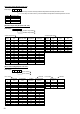
0
1 Controlled
2 Controlled
3 Controlled Controlled
4 Controlled
5 Controlled Controlled
6 Controlled Controlled
7 Controlled Controlled Controlled
8 Controlled
9 Controlled Controlled
A Controlled Controlled
b Controlled Controlled Controlled
C Controlled Controlled
d Controlled Controlled Controlled
E Controlled Controlled Controlled
F Controlled Controlled Controlled Controlled
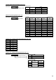
[Operation state] (Request code "0")
Data display
Example) Request code "004"
Dischargetemperature69°C
Refrigerant address "00"
B: Refrigerant address
C: Data display area
D: Request code display area
C 4
Relay output state
Operation mode
[Indoor unit – Control state] (Request code :" 50")
Data display
Operation mode
Display Operation mode
0 STOP • FAN
C COOL • DRY
H HEAT
d Defrost
Relay output state
Display
Power currently
Compressor Four-way valve Solenoid valve
supplied to compressor
Unit No. 4 state
Unit No. 3 state
Unit No. 2 state
Unit No. 1 state
Display State
0 Normal
1 Preparing for heat operation.
2 –
3 –
4 Heater is ON.
5 Anti-freeze protection is ON.
6 Overheat protection is ON.
7 Requestingcompressortoturn OFF.
F There are no corresponding units.
[Outdoor unit – Control state] (Request code "51")
Data display State
0 0 0 0 Normal
0 0 0 1 Preparingforheatoperation.
0 0 0 2 Defrost
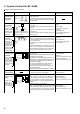
[Compressor – Frequency control state] (Request code "52")
Data display
0 0
Frequency control state
Frequency control state
Frequency control state
Display Current limit control
0 No current limit
1 Primary current limit control is ON.
2 Secondary current limit control is ON.
–
ON
ON
0
1
2
3
4
5
6
7
8
A
–
ON
ON
ON
ON
–
ON
ON
ON
ON
ON
–
ON
ON
ON
ON
2-1. Detail Contents in Request Code