
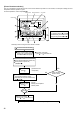
Unit installation


47
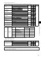
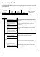
Indication Error
Outdoor controller board
Contents
Error
code
W
1
Inspection method
LED1 (Green) LED2 (Red)
3 blinking 1 blinking
Abnormality of shell thermistor (TH32)
and discharging temperature (TH4)
U2
1
Check if
stop valves are open.
2
Check if
connectors (TH4, TH32, LEV-A and LEV-B) on
outdoor controller board are not disconnected.
3
Check if unit fills with specified amount of refrigeran
4
Measure resistance
values among terminals on indoor
valve and outdoor linear expansion valve with a tester.
Abnormality of
superheat due to low dis-
charge temperature
U7
2 blinking
Abnormal high pressure (High pressure
switch 63H worked.)
U1
1
Check if
indoor/outdoor units have a short cycle on
their air ducts.
2
Check if
connector (63H) on outdoor controller board is
not disconnected.
3
Check if heat exchanger and filter is not dirt .
4
Measure resistance
values among terminals on linear
expansion valve with a tester.
3 blinking
Abnormality of outdoor fan motor rotational
speed
U8
1
Check the
outdoor fan motor.
Protection from overheat operation (TH3) Ud
4 blinking
Compressor over current breaking (Start-up
locked)
UF
1
Check if
stop valves are open.
2
Check looseness,
disconnection, and converse con
-
nection of
compressor wiring.
3
Measure resistance
values among terminals on com
-
pressor with
a tester.
4
Check if
outdoor unit has a short cycle on its air duct.
Compressor over current breaking UP
Abnormality of
current sensor (P.B.) UH
Abnormality of
power module U6
5 blinking
Open/short of discharge thermistor (TH4)
and shell thermistor (TH32)
U3
1
Check if
connectors (TH3, TH4, TH7/6, TH32) on out
-
door controller
board and connector (CN3) on outdoor
power board are not disconnected.
2
Measure resistance
value of outdoor thermistors
Open/short of outdoor thermistors
(TH3, TH6, TH7 and TH8)
U4
6 blinking
Abnormality of heatsink temperature U5
1
Check if
indoor/outdoor units have a short cycle on
their air ducts.
2
Measure resistance
value of outdoor thermistor(TH8).
7 blinking
Abnormality of voltage U9
1
Check looseness,
disconnection, and converse con-
nection of
compressor wiring.
2
Measure resistance
value among terminals on com-
pressor using
a tester.
3
Check the
continuity of contactor (52C).
4
Check if
power supply voltage decreases.
5
Check the
wiring of CN52C.
6
Check the
wiring of CNAF.
4 blinking 1 blinking
Abnormality of room temperature thermis-
tor (TH1)
P1
1
Check
if
connectors (CN20, CN21, CN29 and CN44)
on indoor controller board are not disconnected.
2
Measure resistance
value of indoor thermistors.
Abnormality of pipe temperature thermistor
/Liquid (TH2)
P2
Abnormality of
pipe temperature thermis-
tor/Condenser-Evaporator
P9
2 blinking
Abnormality of drain sensor (DS)
Float switch (FS) connector open
P4
1
Check if
connector (CN31,CN4F) on indoor controller
board is not disconnected.
2
Measure resistance
value of indoor thermistors.
3
Measure resistance
value among terminals on drain-up
machine using a tester.
4
Check if
drain-up machine works.
5
Check drain
function.
Indoor drain overflow protectio P5
3 blinking
Freezing (cooling)/overheating (heating)
protection
P6
1
Check if
indoor unit has a short cycle on its air duct.
2
Check if heat exchanger and filter is not dirt .
3
Measure
resistance
value on indoor and outdoor fan
motors.
4
Check if
the inside of refrigerant piping is not clogged.
4 blinking
Abnormality of pipe temperature P8
1
Check if
indoor thermistors (TH2 and TH5) are not
disconnected from holder.
2
Check if
stop valve is open.
3
Check converse connection of extension pipe. (on
plural
units
connection)
4
Check if
indoor/outdoor connecting wire is connected
correctly. (on plural units connection)
5 blinking
Abnormality of Indoor controller board Fb
1
Replace
indoor controller board.
— — Abnormality of
remote controller board
E1, E2
1
Replace the remote controller.
W
1. Error code displayed on remote controller. Error codes given in ( ) are not displayed on remote controller.