Revision D: • MSZ-GE06/09/12/15/18NA- 9 and MSYGE09/12/15/18NA- 9 have been added. SPLIT-TYPE AIR CONDITIONERS Please void OBH548 REVISED EDITION-C INDOOR UNIT No.
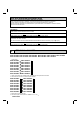
Use the specified refrigerant only Never use any refrigerant other than that specified. Doing so may cause a burst, an explosion, or fire when the unit is being used, serviced, or disposed of. Correct refrigerant is specified in the manuals and on the spec labels provided with our products. We will not be held responsible for mechanical failure, system malfunction, unit breakdown or accidents caused by failure to follow the instructions. Revision A: • MSZ-GE24NA and MSY-GE24NA have been added.
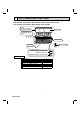
2 PART NAMES AND FUNCTIONS MSZ-GE06NA MSZ-GE09NA MSZ-GE12NA MSZ-GE15NA MSZ-GE18NA MSY-GE09NA MSY-GE12NA MSY-GE15NA MSY-GE18NA Air ¿lter [Catechin air ¿lter (GENA) ] [Nano platinum ¿lter (GENA- 8 , - 9 )] Front panel Air cleaning ¿lter (Anti-Allergy Enzyme Filter) Air inlet Heat exchanger Remote controller Air outlet Horizontal vane Display section Remote control receiving section Operation indicator lamp Emergency operation switch (E.O.
MSZ-GE24NA MSY-GE24NA Front panel Air filter (Nano platinum filter) Air cleaning filter (Electrostatic anti-allergy enzyme filter) Air inlet Air outlet Remote controller Heat exchanger Horizontal vane Display section ACCESSORIES Installation plate Installation plate fixing screw 4 × 25 mm Remote controller holder Fixing screw for 3.
3 SPECIFICATION Indoor model Power supply V, phase, Hz Max. fuse size (time delay)/ Disconnect switch A Min. circuit ampacity A Fan motor F.L.A COOL Dry CFM Airflow (Wet) Super High - High - Med. Low - Quiet HEAT Dry CFM Moisture removal pt./h Sound level Cooling dB(A) Super High - High - Med. Heating dB(A) Low - Quiet Cond. drain connection O.D. in. W Dimensions D in. H Weight Ib.
3-1. OPERATING RANGE (1) POWER SUPPLY Rated voltage 208/230 V 1 phase 60 Hz Indoor unit Guaranteed voltage (V) Min. 187 208 230 Max. 253 (2) OPERATION Intake air temperature (°F) Mode Condition Indoor DB 80 90 67 Standard temperature Maximum temperature Cooling Minimum temperature Maximum humidity Standard temperature Heating Maximum temperature Minimum temperature Outdoor WB 67 73 57 DB 95 115 14 60 67 60 47 75 -4 78% 70 80 70 WB — — — — 43 65 -5 3-2.
4 OUTLINES AND DIMENSIONS MSZ-GE06NA MSZ-GE09NA MSZ-GE12NA MSZ-GE15NA MSZ-GE18NA Unit: inch MSY-GE09NA MSY-GE12NA MSY-GE15NA MSY-GE18NA MSZ-GE06NA- 8 MSZ-GE09NA- 8 MSZ-GE12NA- 8 MSZ-GE15NA- 8 MSZ-GE18NA- 8 MSY-GE09NA- 8 MSY-GE12NA- 8 MSY-GE15NA- 8 MSY-GE18NA- 8 7/8 8-3/8 6-1/8 13-5/16 1/8 1-5/8 10 9-1/8 6-1/8 2-3/8 13-9/16 Air in Indoor unit 2-1/8 Wall hole ø2-9/16 Installation plate 24-3/8 1-5/8 5-1/8 4/3/16 Air out 9 9 9 MSZ-GE12NAMSY-GE15NA- 9 9 Insulation Liquid line Gas line Drai
MSZ-GE24NA MSY-GE24NA 8-7/8 7/16×3/4 Oblong hole 8-7/8 27/32 7/16×1 Oblong hole 5-1/16 Installation plate 4-5/16 1-15/16 7-27/32 19-3/4 Air in 1/8 7-27/32 1-3/4 Indoor unit 9-3/8 17-5/16 Installation plate 4-3/8 1-3/4 9-3/8 10-3/16 11 3/16 11-1/16 9-7/16 43-5/16 42-7/8 Wall hole Ø3 Piping 33-1/8 7-1/8 2-9/16 ( 70° ) 3/4 4-7/8 6-5/16 7-1/4 Drain hose 2-1/2 OBH548D 2-9/16 1-3/16 2-9/16 8 Piping 2-1/2 Air out 6-1/4 2-5/16 3 1/8 2-1/2 3-15/16 1/2 2-5/8 12-13/16 2-9/1
5 WIRING DIAGRAM MSZ-GE06NA MSZ-GE09NA MSZ-GE12NA MSZ-GE15NA MSZ-GE18NA MSY-GE09NA MSY-GE12NA MSY-GE15NA MSY-GE18NA MSZ-GE06NAMSY-GE09NA- OBH548D 8 8 MSZ-GE09NAMSY-GE12NA- 8 8 MSZ-GE12NAMSY-GE15NA- 9 8 8 MSZ-GE15NAMSY-GE18NA- 8 8 MSZ-GE18NA- 8
MSZ-GE06NAMSY-GE09NA- 9 9 MSZ-GE09NAMSY-GE12NA- 9 9 MSZ-GE12NAMSY-GE15NA- MSZ-GE24NA MSY-GE24NA OBH548D 10 9 9 MSZ-GE15NAMSY-GE18NA- 9 9 MSZ-GE18NA- 9
6 REFRIGERANT SYSTEM DIAGRAM MSZ-GE06NA MSZ-GE09NA MSZ-GE12NA MSZ-GE15NA MSZ-GE18NA MSY-GE09NA MSY-GE12NA MSY-GE15NA MSY-GE18NA Refrigerant pipe ø3/8 (MSZ-GE06/09/12NA, MSY-GE09/12NA) ø1/2 (MSZ-GE15/18NA, MSY-GE15/18NA) (with heat insulator) Indoor heat exchanger Indoor coil thermistor RT12 (main) Flared connection Indoor coil thermistor RT13 (sub) Room temperature thermistor RT11 Flared connection Refrigerant pipe ø1/4 (with heat insulator) Refrigerant flow in cooling Refrigerant flow in heating M
7 SERVICE FUNCTIONS MSZ-GE06NA MSZ-GE09NA MSZ-GE12NA MSZ-GE15NA MSZ-GE18NA MSZ-GE24NA MSY-GE09NA MSY-GE12NA MSY-GE15NA MSY-GE18NA MSY-GE24NA 7-1. TIMER SHORT MODE For service, the set time can be shortened by bridging of JPG and JPS the indoor electronic control P.C. board. The time will be shortened as follows. (Refer to 9-7.) • The set time for the ON/OFF timer can be reduced to 1 second for each minutes.
7-3. AUTO RESTART FUNCTION When the indoor unit is controlled with the remote controller, the operation mode, the set temperature, and the fan speed are memorized by the indoor electronic control P.C. board. “AUTO RESTART FUNCTION” automatically starts operation in the same mode just before the shut-off of the main power. Operation If the main power has been cut, the operation settings remain. After the power is restored, the unit restarts automatically according to the memory.
8 MICROPROCESSOR CONTROL MSZ-GE06NA MSZ-GE09NA MSZ-GE12NA MSZ-GE15NA MSZ-GE18NA MSZ-GE24NA MSY-GE09NA MSY-GE12NA MSY-GE15NA MSY-GE18NA MSY-GE24NA WIRELESS REMOTE CONTROLLER E.g.
INDOOR UNIT DISPLAY SECTION Operation Indicator lamp The operation indicator at the right side of the indoor unit indicates the operation state. • The following indication applies regardless of shape of the indication.
8-3. HEAT ( ) OPERATION (MSZ) (1) Press OPERATE/STOP (ON/OFF) button. OPERATION INDICATOR lamp of the indoor unit turns ON with a beep tone. (2) Select HEAT mode with OPERATION SELECT button. (3) Press TEMPERATURE buttons (TOO WARM or TOO COOL button) to select the desired temperature. The setting range is 61 ~ 88°F (16 ~ 31°C). 1.
8-6. AUTO CHANGE OVER ··· AUTO MODE OPERATION (MSZ) Once desired temperature is set, unit operation is switched automatically between COOL and HEAT operation. Mode selection (1) Initial mode When unit starts the operation with AUTO operation from OFF: • If the room temperature is higher than the set temperature, operation starts in COOL mode. • If the room temperature is equal to or lower than the set temperature, operation starts in HEAT mode.
) mode (4) VANE AUTO ( The microprocessor automatically determines the vane angle to make the optimum room temperature distribution. In COOL and DRY operation Vane angle is fixed to Horizontal position. In HEAT operation Vane angle is fixed to Angle 5. Horizontal position 5 (5) STOP (operation OFF) and ON TIMER standby In the following cases, the horizontal vane returns to the closed position. (a) When OPERATE/STOP (ON/OFF) button is pressed (POWER OFF).
8-8. TIMER OPERATION 1. How to set the time (1) Check that the current time is set correctly. NOTE: Timer operation will not work without setting the current time. Initially “0:00 AM” blinks at the current time display of TIME MONITOR, so set the current time correctly with CLOCK SET button. How to set the current time (a) Press the CLOCK set button. (b) Press the TIME SET buttons ( ) to set the current time.
8-9. SMART SET ( ) OPERATION (MSZ-GE06/09/12/15/18NA MSY-09/12/15/18NA) 1. How to SET SMART SET operation (1) Press OPERATE/STOP (ON/OFF) button. (2) Select COOL, HEAT (MSZ) or ECONO COOL mode. (3) Press SMART SET button. (4) Set the temperature, fan speed, and airflow direction for SMART SET operation. NOTE: • SMART SET operation cannot be selected during DRY or AUTO mode operation. • The setting range of HEAT mode in SMART SET operation is between 50°F (10°C) and 61 - 87°F (16 - 31°C) (MSZ).
9 TROUBLESHOOTING MSZ-GE06NA MSZ-GE09NA MSZ-GE12NA MSZ-GE15NA MSZ-GE18NA MSZ-GE24NA MSY-GE09NA MSY-GE12NA MSY-GE15NA MSY-GE18NA MSY-GE24NA 9-1. CAUTIONS ON TROUBLESHOOTING 1. Before troubleshooting, check the following 1) Check the power supply voltage. 2) Check the indoor/outdoor connecting wire for miswiring. 2.
9-2. FAILURE MODE RECALL FUNCTION Outline of the function This air conditioner can memorize the abnormal condition which has occurred once. Even though LED indication listed on the troubleshooting check table (9-4.) disappears, the memorized failure details can be recalled. 1.
2. Indoor unit failure mode table Upper lamp of OPAbnormal point ERATION INDICA(Failure mode) TOR lamp Not lighted Normal Condition Remedy — The room temperature thermistor short or 1-time flash every Room temperature open circuit is detected every 8 seconds dur0.5-second thermistor ing operation. Indoor coil 2-time flash The indoor coil thermistor short or open circuit 2.5-second OFF is detected every 8 seconds during operation.
9-3. INSTRUCTION OF TROUBLESHOOTING Start Indoor unit operates. Outdoor unit does not operate. Outdoor unit operates only in Test Run operation. Outdoor unit does not operate even in Test Run operation. Indoor unit operates. Outdoor unit does not operate normally. Unit does not operate normal operation in COOL or HEAT mode. Indoor unit does not receive the signal from remote controller. Indoor unit operates, when EMERGENCY OPERATION switch is pressed.
9-4. TROUBLESHOOTING CHECK TABLE Before taking measures, make sure that the symptom reappears for accurate troubleshooting. When the indoor unit has started operation and detected an abnormality of the following condition (the first detection after the power ON), the indoor fan motor turns OFF and OPERATION INDICATOR lamp flashes. OPERATION INDICATOR Lighted Blinking Not lighted No.
OPERATION INDICATOR No. Abnormal point Operation indicator lamp Symptom Remedy Condition Upper lamp lights and lower lamp flashes. 1 MXZ type Operation mode setting The operation mode of the each indoor unit Outdoor unit is differently set to COOL (includes DRY) and • Unify the operation mode. operates but HEAT at the same time, the operation mode Refer to outdoor unit service indoor unit does of the indoor unit that has operated at first has manual. not operate. the priority. 2.
9-6. TROUBLESHOOTING FLOW A Check of indoor fan motor MSZ-GE06/09/12/15/18NA MSY-GE09/12/15/18NA The indoor fan motor error has occurred, and the indoor fan does not operate. Turn OFF the power supply. Pay enough attention to the high voltage on the fan motor connector. Is there any foreign matter that interferes the rotation of the line flow fan? No Yes Remove the foreign matter and adjust the line flow fan.
MSZ-GE24NA MSY-GE24NA The indoor fan motor error has occurred, and the indoor fan does not operate. Turn OFF the power supply. Pay enough attention to the high voltage on the fan motor connector. Is there any foreign matter that interferes the rotation of the line flow fan? Yes Remove the foreign matter and adjust the line flow fan. Is there 294/325 VDC between CN211 (+) and (–) ? No Turn ON the power supply, wait 5 seconds or more, and then press EMERGENCY OPERATION switch.
B Check of remote controller and indoor electronic control P.C. board Check if the remote controller is exclusive for this air conditioner. MSZ-GE06/09/12/15/18NA MSY-GE09/12/15/18NA Press OPERATE/STOP (ON/OFF) button on the remote controller. Is LCD display on the remote controller visible? Yes No (Not clear) 1 Look at the image of the signal transmitting section of the remote controller through the monitor of a digital camera or a camera phone.
C Check of indoor P.C. board and indoor fan motor MSZ-GE06/09/12/15/18NA MSY-GE09/12/15/18NA Turn OFF the power supply. Remove indoor fan motor connector CN211 from indoor power P.C. board and vane motor connector CN151 from the indoor electronic control P.C. board and turn ON the power supply. Does the unit operate with the remote controller? Does OPERATION INDICATOR lamp light up by pressing EMERGENCY OPERATION switch? No Yes Measure the resistance of indoor fan motor. (Refer to 9-5.
MSZ-GE24NA MSY-GE24NA Turn OFF the power supply. Remove indoor fan motor connector CN211 and vane motor connector CN151 from the indoor electronic control P.C. board and turn ON the power supply. Short circuit: Replace the indoor fan motor. Measure the resistance between CN211 and of the indoor fan motor connector. Yes Does the unit operate with the remote controller? Does OPERATION INDICATOR lamp light up by pressing EMERGENCY OPERATION switch? Measure the resistance of the horizontal vane motor coil.
D How to check miswiring and serial signal error MSZ-GE06/09/12/15/18NA MSY-GE09/12/15/18NA Turn OFF the power supply. Is there rated voltage in the power supply? Yes Check the power supply. No Turn ON the power supply. Yes Is there rated voltage between outdoor terminal block S1 and S2? No Check the wiring. Press EMERGENCY OPERATION switch once.
MSZ-GE24NA MSY-GE24NA Turn OFF the power supply. Is there rated voltage in the power supply? Yes Check the power supply. No Turn ON the power supply. Is there rated voltage between outdoor terminal block S1 and S2? Yes No Check the wiring. Press EMERGENCY OPERATION switch once. Does the OPERATION INDICATOR lamp light up? Yes Is serial signal error indicated 6 minutes later? Yes A Turn OFF the power supply.
E Electromagnetic noise enters into TV sets or radios Is the unit grounded? Yes Is the distance between the antennas and the indoor unit within 9.91 ft.(3 m), or is the distance between the antennas and the outdoor unit within 9.91 ft.(3 m)? Ground the unit. No Yes Extend the distance between the antennas and the indoor unit, and/or the antennas and the outdoor unit. Yes Extend the distance between the TV sets and/or radios and the indoor unit, or the TV sets or radios and the outdoor unit.
9-7. Test point diagram and voltage MSZ-GE06/09/12/15/18NA/NA- 8 MSY-GE09/12/15/18NA/NA1. Indoor power P.C. board, Indoor terminal P.C. board Indoor terminal P.C. board Fuse (F11)( ) 8 Indoor power P.C. board Varistor (NR11) Resistor (R111) Indoor fan motor (CN211) 294/325 VDC (–) GND (highvoltage DC) 15 VDC (+)3-6 VDC (+)0-6 V Terminal block Connector to indoor electronic control P.C. board (CN20A) 5 VDC 12 VDC GND Please replace the fuse after removing the indoor terminal P.C.
MSZ-GE06/09/12/15/18NA- 8 MSY-GE09/12/15/18NA- 8 Indoor electronic control P.C. board Timer short mode point JPG JPS (Refer to 7-1.) Room temperature thermistor RT11 (CN111) Indoor coil thermistor RT12, RT13 (CN112) GND Connector to Indoor power P.C. board (CN10A) 12 VDC 5 VDC Emergency operation switch (E.O.SW) (SW1) OBH548D To disable "Auto restart function", solder the Jumper wire to JR07. (Refer to 7-3.
MSZ-GE06/09/12/15/18NA- 9 MSY-GE09/12/15/18NA- 9 Indoor power P.C. board, Indoor terminal P.C. board Indoor terminal P.C. board Indoor power P.C. board Varistor (NR11) Fuse (F11)( ) Resistor (R111) Indoor fan motor (CN211) (+)0-6 V (+)3-6 VDC 15 VDC (–) GND (highvoltage DC) 294/325 VDC Terminal block Connector to indoor electronic control P.C. board (CN20A) GND 5 VDC 12 VDC Please replace the fuse after removing the indoor terminal P.C. board from the electrical box.
MSZ-GE24NA 3. Indoor terminal P.C. board, Indoor electronic control P.C. board, Power monitor receiver SW P.C. board Indoor terminal P.C. board Indoor electronic control P.C. board Fuse Terminal (F11)( ) block Varistor (NR11) To disable "Auto restart function", solder the Jumper wire to JR07. Resistor (R111) (Refer to 7-3.) Indoor coil thermistor RT12, RT13 12 VDC (CN112) Room temperature thermistor RT11 (CN111) JR07 JR77 Vane motor (CN151, CN152) Power monitor receiver SW P.C.
MSY-GE24NA Indoor terminal P.C. board, Indoor electronic control P.C. board, Power monitor receiver SW P.C. board Indoor terminal P.C. board Terminal Fuse (F11)( ) block Varistor (NR11) Indoor electronic control P.C. board Indoor coil thermistor To disable "Auto restart function", RT12, RT13 12 VDC solder the Jumper wire to JR07. (Refer to 7-3.
10 DISASSEMBLY INSTRUCTIONS <"Terminal with locking mechanism" Detaching points> The terminal which has the locking mechanism can be detached as shown below. There are two types (refer to (1) and (2)) of the terminal with locking mechanism. The terminal without locking mechanism can be detached by pulling it out. Check the shape of the terminal before detaching. (1) Slide the sleeve and check if there is a locking lever or not.
OPERATING PROCEDURE PHOTOS 2. Removing the indoor electronic control P.C. board and the room temperature thermistor Photo 2 (1) Remove the panel (Refer to 1.) and the corner box. (2) Remove the screw of the V.A. clamp and the V.A. clamp. (3) Loosen the screw of the indoor/outdoor connecting wire and remove the indoor/outdoor connecting wire. (4) Remove the screw of the electrical cover and the electrical cover. (5) Open the indoor electronic control P.C.
OPERATING PROCEDURE PHOTOS 4. Removing the nozzle assembly Photo 5 (1) Remove the panel (Refer to 1.) and the corner box. (2) Remove the indoor/outdoor connecting wire (Refer to 2 (2)-(7).). (3) Remove the indoor electronic control P.C. board holder. (4) Pull out the drain hose from the nozzle assembly and remove the nozzle assembly. 5. Removing the horizontal vane motor (1) Remove the nozzle assembly. (Refer to 5.) (2) Remove the screws of the horizontal vane motor unit.
OPERATING PROCEDURE PHOTOS 6. Removing the indoor fan motor, the indoor coil thermistor, and the line flow fan Photo 6 (1) Remove the panel (Refer to 1.) and the corner box. (2) Remove the indoor electronic control P.C. board holder, the electrical box and the nozzle assembly. (3) Remove the screws fixing the motor bed. (4) Loosen the screw fixing the line flow fan. (5) Remove the motor bed together with fan motor and motor band. (6) Release the hooks of the motor band. Remove the motor band.
10-2. MSZ-GE24NA MSY-GE24NA NOTE: Turn OFF the power supply before disassembly. OPERATING PROCEDURE PHOTOS 1. Removing the panel Photo 1 (1) Remove the horizontal vanes. (2) Remove the screw caps of the panel. Remove the screws of the panel. (3) Hold the lower part of both ends of the panel and pull it slightly toward you, and then remove the panel by pushing it upward. Horizontal vanes 2. Removing the indoor electronic control P.C. board, the power monitor receiver SW P.C.
OPERATING PROCEDURE PHOTOS 4. Removing the nozzle assembly Photo 4 (1) Remove the panel (Refer to 1.) and the corner box. (2) Remove the V.A. clamp, and then the indoor/outdoor connecting wire. (Refer to 2 (2)-(4).) (3) Remove the electrical cover. (Photo 2) (4) Disconnect the following connectors on the electronic control P.C. board: CN151 (Horizontal vane motor) CN152 (Vertical vane motor) (5) Remove the power monitor receiver holder.
OPERATING PROCEDURE PHOTOS 7. Removing the water cut, the indoor fan motor, the indoor coil thermistor, and the line flow fan Photo 8 (1) Remove the panel (Refer to 1.) and the corner box. (2) Remove the power monitor receiver holder, the electrical box and the nozzle assembly. (Refer to 3 and 4.) (3) Remove the screw of the water cut and remove the water cut. (4) Remove the screws fixing the motor bed. (5) Loosen the screw fixing the line flow fan.
Fixing the indoor coil thermistor There are 2 forms of parts for fixing the indoor coil thermistor. Clip shape Holder shape When fixing the indoor coil thermistor to the clip-shape/holder-shape part, the lead wire should point down. About the same length Position and procedure for mounting the clip-shape part 1. Set the indoor coil thermistor in the center of the clip-shape part. 2. Check the (marked) mounting position. 3.Mount the clip-shape part.
HEAD OFFICE: TOKYO BLDG., 2-7-3, MARUNOUCHI, CHIYODA-KU, TOKYO 100-8310, JAPAN © Copyright 2009 MITSUBISHI ELECTRIC CO.,LTD Distributed in Oct. 2014. No. OBH548 REVISED EDITION-D Distributed in Jul. 2011. No. OBH548 REVISED EDITION-C Distributed in Apr. 2011. No. OBH548 REVISED EDITION-B Distributed in Sep. 2010. No. OBH548 REVISED EDITION-A 5 Distributed in Jul. 2009. No. OBH548 5 Made in Japan New publication, effective Oct. 2014 Specifications subject to change without notice.