
M-Series MSZ-GE Engineering Manual
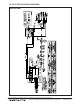


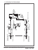

Table Of Contents
- Contents
- 1. INDOOR UNITS
- 2. OUTDOOR UNITS
- 3. SYSTEM
- 3-1. SPECIFICATIONS
- 3-2. EXTERNAL DIMENSIONS
- 3-3. CENTER OF GRAVITY
- 3-4. ELECTRICAL WIRING DIAGRAMS
- 3-5. REFRIGERANT SYSTEM DIAGRAMS
- 3-6. CAPACITY CORRECTION CURVE BY TEMPERATURE
- 3-7. CAPACITY CORRECTION TABLE BY TEMPERATURE
- 3-8. CAPACITY CORRECTION CURVE BY REFRIGERANT PIPING LENGTH
- 3-9. CAPACITY CORRECTION TABLE BY REFRIGERANT PIPING LENGTH
- 3-10. CHARGE CALCULATIONS
- 3-11. AIR FLOW DATA
- 3-12. SOUND PRESSURE LEVELS
- 3-13. STANDARD OPERATION RANGE
- 3-14. MAXIMUM HEATING CAPACITY IN LOW AMBIENT TEMPERATURE
- 3-15. ACCESSORIES

MSZ-GE-NA-26
M-Series - MSZ/MUZ-GE-NA Heat Pump Systems (August 2014)
Due to continuing improvement, above specication may be subject to change without notice.
© 2014 Mitsubishi Electric US, Inc.
3-5. REFRIGERANT SYSTEM DIAGRAMS
Outdoor
heat
exchanger
Flared connection
Defrost
thermistor
RT61
(MUZ)
Discharge
temperature
thermistor
RT62
Flared connection
Stop valve
(with strainar)
Stop valve
(with service port)
Refrigerant flow in cooling
Compressor
4-way valve
Refrigerant flow in heating
(MUZ)
Refrigerant pipe ø3/8 (GE12NA)
Refrigerant pipe ø1/2 (GE15NA)
(with heat insulator)
Refrigerant pipe ø1/4
(with heat insulator)
R.V. coil
(MUZ)
heating ON
cooling OFF
Strainer
#100
Capillary tube
O.D. 0.118 × I.D. 0.071
× 23-5/8
(ø
3.0
× ø
1.8
×
600
)
(×2)
LEV
Ambient
temperature
thermistor
RT65
Muffler
Capillary tube
O.D. 0.118 × I.D. 0.079
× 9-7/16
(ø3.0 × ø2.0
×
240)
Outdoor heat
exchanger
temperature
thermistor
RT68
Muffler
Service port
Service port
MUZ-GE12NA MUZ-GE15NA-1