M-SERIES SINGLE ZONE SYSTEMS MSZ-GE-NA WALL-MOUNT HEAT PUMP SYSTEMS 1. INDOOR UNITS.............................................................................................................................................MSZ-GE-NA-3 2. OUTDOOR UNITS.........................................................................................................................................MSZ-GE-NA-4 3. SYSTEM......................................................................................................
M-SERIES SINGLE ZONE SYSTEMS 3-7. CAPACITY CORRECTION TABLE BY TEMPERATURE..........................................................................MSZ-GE-NA-33 (1) Cooling Capacity...................................................................................................................................MSZ-GE-NA-33 (2) Heating Capacity .................................................................................................................................
1. INDOOR UNITS • MSZ-GE06NA-8* • MSZ-GE09NA-8 • MSZ-GE12NA-8 • MSZ-GE15NA-8 • MSZ-GE18NA-8 • MSZ-GE24NA *The MSZ-GE06NA-8 is only compatible with the multi-split MXZ heat pump systems. Due to continuing improvement, above specification may be subject to change without notice. M-Series - MSZ/MUZ-GE-NA Heat Pump Systems (August 2014) © 2014 Mitsubishi Electric US, Inc.
2. OUTDOOR UNITS • MUZ-GE09NA • MUZ-GE12NA • MUZ-GE15NA-1 • MUZ-GE18NA-1 • MUZ-GE24NA Due to continuing improvement, above specification may be subject to change without notice. MSZ-GE-NA-4 M-Series - MSZ/MUZ-GE-NA Heat Pump Systems (August 2014) © 2014 Mitsubishi Electric US, Inc.
3.
3-1. SPECIFICATIONS MSZ-GE06NA-8 MSZ-GE09NA-8 MSZ-GE12NA-8 MSZ-GE15NA-8 MSZ-GE18NA-8 MSZ-GE06NA-8 Model name Power supply MSZ-GE09NA-8 V, phase, Hz 208/230, 1, 60 Max. fuse size (time delay)/ Disconnect switch A 15 Min. circuit ampacity A 1.0 Blower Motor (ECM) F.L.A 0.76 Airflow Super High - High - Med. Low - Quiet COOL Dry CFM (Wet) HEAT Dry Moisture removal 399-321-237-170-145 (364-286-201-134-109) CFM 406-321-233-170145 pt./h – 1.5 2.5 0.82 0.74 0.
3-1. SPECIFICATIONS MSZ-GE24NA MSZ-GE24NA Model name Power supply V, phase, Hz 208/230, 1, 60 Max. fuse size (time delay)/ Disconnect switch A 20 Min. circuit ampacity A 1.0 Blower Motor (ECM) F.L.A 0.76 COOL Dry (Wet) CFM 738-628-469-388 (661-562-420-347) HEAT Dry CFM 406-321-237-170-145 pt./h 5.1 Airflow Powerful - High - Med - Low Moisture removal Sensible Heat Factor Sound level Powerful - High - Med - Low 0.75 Cooling dB(A) 53-49-41-34 Heating dB(A) 52-49-41-32 Cond.
3-1. SPECIFICATIONS MUZ-GE09NA-1 MUZ-GE12NA Model name MUZ-GE09NA MUZ-GE12NA Cooling 1 Btu/h 9,000 ( 3,800 ~ 12,200 ) 12,000 ( 3,800 ~ 13,600 ) Heating 47 1 Btu/h 10,900 ( 4,500 ~ 14,100 ) 14,400 ( 5,500 ~ 18,100 ) Capacity Heating 17 2 Btu/h 8,700 11,200 Power consumption Cooling 1 W 660 (205~1,200) 960 (205~1,300) Rated (Minimum~Maximum) Heating 47 1 W 760 (255~1,200) 1,170 (340~1,660) Power consumption Heating 17 2 W 950 1,200 EER 1 [SEER] 3 Cooling 13.6 [ 21.0 ] 12.
3-1.
3-1. SPECIFICATIONS MUZ-GE24NA MUZ-GE24NA Model name Capacity Cooling 1 Btu/h 22,500(8,200 ~ 31,400) Rated (Minimum~Maximum) Heating 47 1 Btu/h 27,600(7,500 ~ 36,900) Capacity Rated (Maximum) Heating 17 2 Btu/h 16,000 (24,600) Power consumption Cooling 1 W 1,800 (570 ~ 3,580) Rated (Minimum~Maximum) Heating 47 1 W 2,340 (520 ~ 3,650) Power consumption Heating 17 2 W 1,770 (3,290) EER 1 [SEER] 3 Cooling 12.5 [19.0] HSPF IV 4 Heating 10.0 COP Heating 1 3.
3-1. SPECIFICATIONS Efficiency ratings Outdoor Unit Indoor Unit SEER EER HSPF COP COP Energy @ 47° F @ 17° F Star Tax Credit Most Efficient WALL-MOUNT HEAT PUMP MUZ-GE09NA MSZ-GE09NA-8 21.00 13.6 10 4.20 2.76 Yes Yes Yes MUZ-GE12NA MSZ-GE12NA-8 20.25 12.5 10 3.60 2.86 Yes Yes Yes MUZ-GE15NA-1 MSZ-GE15NA-8 21.00 13.0 10 3.30 2.88 Yes Yes Yes MUZ-GE18NA-1 MSZ-GE18NA-8 19.20 10.5 10 3.32 2.70 MUZ-GE24NA MSZ-GE24NA 19.00 12.5 10 3.46 2.
2-3/4 2- 5/16 1-3/4 9-1/8 3/4 1-15/16 2-3/16 24-3/8 31-7/16 30-15/16 1-15/16 5-1/8 Indoor unit 8-3/8 1-5/8 1/4 1-5/8 3/16 2-3/16 6 - 1/4 11-5/8 1-11/16 2-3/8 Air out 5/16 Installation plate 3-15/16 Air in 13-5/16 4-3/8 4/3/16 6-1/8 8-7/8 13-9/16 1-5/8 Piping 3-1/8 7/8 10 7/16×13/16 Oblong hole 2-1/8 Wall hole ø2-9/16 Drain hose Installation plate 6-1/8 8-7/8 8-5/16 1/8 1-5/8 3-1/8 2-3/16 2-11/16 9-15/16 MSZ-GE-NA-12 9-1/8 7/16×1 Oblong hole 3-2.
2-9/16 2-5/16 2-1/2 9-3/8 3/4 3 2-9/16 33-1/8 43-5/16 42-7/8 7-1/8 12-13/16 1-3/16 2-9/16 Indoor unit 3/16 1-15/16 1-3/4 11-1/16 9-7/16 2-1/2 1/2 Air out 3-15/16 3/16 6-1/4 8-1/4 2-1/2 4-7/8 6-5/16 7-1/4 19-3/4 Insulation Liquid line Gas line Drain hose ( 70° ) Air in 7/16×1 Oblong hole 5-1/16 Piping 7-27/32 8-7/8 2-9/16 17-5/16 4-5/16 7/16×3/4 Oblong hole Wall hole Ø3 4-3/8 Ø2 O.
11-1/32 handle 7/8 Air in 1-3/4 13/32 5-15/16 31-1/2 19-11/16 11-29/32 Air out Air in 15-3/4 1-5/8 13-9/16 11/16 13/16 Oval hole 1-9/16 2- 3/8 Drain hole 12 ~ 12-3/4 2-23/32 2 MSZ-GE-NA-14 5-7/8 29/32 6-23/32 11-1/4 8 re r mo in. o :1/4 (flared) :3/8 (flared) (GE09/12) 1/2 (flared) (GE15) .o 4 in r mo re 14 in. or mo re Basically open 4 inch or more without any obstruction in front and on both sides of the unit. Open two sides of left, right, or rear side.
M-Series - MSZ/MUZ-GE-NA Heat Pump Systems (August 2014) 33-7/16 13 Air in Drain 3 holes (ø1-5/16) 2 16-15/16 11-25/32 2-19/32 Air in 4-25/32 33-1/16 Air out 19-11/16 20-9/32 3-3/16 . or 4 in re mo Liquid:1/4(flared) Gas :1/2(flared) 14 in.
2 17-25/32 13 34-5/8 6-7/8 4-5/16 33-1/16 19-11/16 Air out Air in 1-5/8 3-3/16 2-holes 13/32 13/16 Drain hole 1-9/16 . or 4 in 6-1/2 16-7/16 in m . or ore *2 Clear *1 14 in. or mo re 7-11/16 re mo r o n. 4i 35 Gas refrigerant pipe joint Refrigerant pipe (flared) Ø 5/8 Liquid refrigerant pipe joint Refrigerant pipe (flared) Ø 3/8 Service panel *2 When any 2 sides of left, right and rear of the unit are clear 20 re mo *1 20 in.
3-3.
3-4. ELECTRICAL WIRING DIAGRAMS MSZ-GE09NA-8 MSZ-GE12NA-8 MSZ-GE15NA-8 MSZ-GE18NA-8 Due to continuing improvement, above specification may be subject to change without notice. MSZ-GE-NA-18 M-Series - MSZ/MUZ-GE-NA Heat Pump Systems (August 2014) © 2014 Mitsubishi Electric US, Inc.
3-4. ELECTRICAL WIRING DIAGRAMS MSZ-GE24NA MSY-GE24NA MSZ-GE24NA Due to continuing improvement, above specification may be subject to change without notice. M-Series - MSZ/MUZ-GE-NA Heat Pump Systems (August 2014) © 2014 Mitsubishi Electric US, Inc.
3-4. ELECTRICAL WIRING DIAGRAMS MUZ-GE09NA MUZ-GE12NA Due to continuing improvement, above specification may be subject to change without notice. MSZ-GE-NA-20 M-Series - MSZ/MUZ-GE-NA Heat Pump Systems (August 2014) © 2014 Mitsubishi Electric US, Inc.
3-4. ELECTRICAL WIRING DIAGRAMS MUZ-GE15NA- 1 11 MUZ-GE15NA-1 Due to continuing improvement, above specification may be subject to change without notice. M-Series - MSZ/MUZ-GE-NA Heat Pump Systems (August 2014) © 2014 Mitsubishi Electric US, Inc.
3-4. ELECTRICAL WIRING DIAGRAMS MUZ-GE18NA- 1 13 MUZ-GE18NA-1 Due to continuing improvement, above specification may be subject to change without notice. MSZ-GE-NA-22 M-Series - MSZ/MUZ-GE-NA Heat Pump Systems (August 2014) © 2014 Mitsubishi Electric US, Inc.
3-4. ELECTRICAL WIRING DIAGRAMS MUZ-GE24NA Due to continuing improvement, above specification may be subject to change without notice. M-Series - MSZ/MUZ-GE-NA Heat Pump Systems (August 2014) © 2014 Mitsubishi Electric US, Inc.
3-5.
© 2014 Mitsubishi Electric US, Inc. M-Series - MSZ/MUZ-GE-NA Heat Pump Systems (August 2014) Refrigerant pipe ø1/4 (with heat insulator) Flared connection Flared connection Refrigerant pipe ø3/8 (with heat insulator) Stop valve (with strainar) Capillary tube O.D. 0.118 × I.D. 0.079 × 9-7/16 LEV (ø3.0 × ø2.0 × 240) Ambient temperature thermistor RT65 R.V.
MSZ-GE-NA-26 Refrigerant pipe ø1/4 (with heat insulator) Flared connection Flared connection Stop valve (with strainar) Capillary tube O.D. 0.118 × I.D. 0.079 LEV × 9-7/16 (ø3.0 × ø2.0 × 240) Defrost thermistor RT61 (MUZ) Compressor Service port Muffler Ambient temperature thermistor RT65 Outdoor heat exchanger temperature thermistor RT68 Refrigerant flow in cooling Refrigerant flow in heating (MUZ) R.V. coil (MUZ) heating ON cooling OFF Strainer #100 Outdoor heat exchanger Capillary tube O.
© 2014 Mitsubishi Electric US, Inc. Refrigerant pipe ø1/4 (with heat insulator) Flared connection Flared connection Refrigerant pipe ø1/2 (with heat insulator) Stop valve (with strainar) Receiver Service port Stop valve (with service port) Strainer #100 (ø3.6×ø2.4×50) O.D. 0.142 × I.D. 0.094 × 1-31/32 Capillary tube LEV Ambient temperature thermistor RT65 R.V.
MSZ-GE-NA-28 Refrigerant pipe ø1/4 (with heat insulator) Flared connection Flared connection Stop valve Strainer #100 Service port O.D. 0.142 × I.D. 0.094 × 1-31/32 (ø3.6 × ø2.
3-6. CAPACITY CORRECTION CURVE BY TEMPERATURE (1) Cooling MUZ-GE09NA MUZ-GE12NA SHF at rating condition = 0.73 Airflow = 350 CFM SHF at rating condition = 0.76 Airflow = 307 CFM r inta ke air 11 WB t empe 10 rature (°F) 9 71 67 63 8 Total power consumption (kW) 7 0.7 0.6 e air W tak r in Indoo °F) ture ( pera B tem 71 67 63 0.
3-6. CAPACITY CORRECTION CURVE BY TEMPERATURE Total power consumption (kW) MUZ-GE18NA-1 2.0 SHF at rating condition = 0.71 Airflow = 498 CFM 1.9 71 67 63 1.8 1.7 1.6 1.5 1.4 1.3 65 e air r intak Indoo rature mpe WB te (°F) 75 85 95 105 Outdoor intake air DB temperature (°F) 115 Total power consumption (kW) MUZ-GE24NA 2.2 2.1 2.0 1.9 1.8 1.7 1.6 1.5 1.4 1.3 65 SHF at rating condition = 0.
3-6. CAPACITY CORRECTION CURVE BY TEMPERATURE (2) Heating Total capacity ( 103 Btu/h) 14 12 e tak r in oo Ind 8 °F) ur rat pe em Bt D air 65 70 75 e( 13 11 10 9 MUZ-GE12NA Airflow = 413 CFM 15 Airflow = 413 CFM 20 Total capacity ( 103 Btu/h) MUZ-GE09NA 16 12 r in oo Ind e tak air DB ure rat e mp te ) 65 70 75 (°F 8 6 5 4 1.0 1.3 75 70 65 0.8 0.6 r inta 5 15 tu pera B tem D ke air Indoo 0.
3-6. CAPACITY CORRECTION CURVE BY TEMPERATURE Total power consumption (kW) MUZ-GE18NA-1 2.2 2.0 1.8 1.6 1.4 1.2 1.0 0.8 0.6 Airflow = 512 CFM take air Indoor in 0 75 70 65 F) rature (° DB tempe 10 20 30 40 50 60 Outdoor intake air WB temperature (°F) 70 Total power consumption (kW) MUZ-GE24NA Airflow = 738 CFM 3.0 75 70 65 2.6 2.2 1.8 take Indoor in 1.4 1.
© 2014 Mitsubishi Electric US, Inc. 13.1 17.2 16.2 15.3 21.1 20.0 18.7 71 67 63 71 67 63 14.7 71 63 9.8 63 13.9 10.4 67 67 11.0 TC 71 IWB (˚ F) 15.8 14.2 12.2 14.2 13.0 11.4 11.4 10.3 8.9 9.4 8.6 7.6 SHC 75 1.31 1.38 1.46 0.86 0.91 0.96 0.77 0.81 0.85 0.53 0.55 0.59 TPC 17.4 18.6 19.7 14.1 15.1 16.0 12.1 13.0 13.7 9.1 9.7 10.3 TC NOTE: 1.
MSZ-GE-NA-34 10.3 65 9.1 75 9.8 9.0 65 70 8.6 7.9 75 70 7.2 65 6.3 75 6.8 5.5 65 70 5.2 4.8 TC 70 75 IDB (˚ F) 5 0.59 0.62 0.64 0.57 0.60 0.63 0.63 0.66 0.69 0.41 0.43 0.45 TPC 13.0 12.7 11.9 11.3 11.1 10.4 9.1 8.9 8.4 6.9 6.7 6.3 TC 0.75 0.78 0.81 0.73 0.76 0.79 0.81 0.84 0.87 0.52 0.55 0.57 TPC 15 16.2 15.5 14.9 14.1 13.5 13.1 11.3 10.8 10.4 8.6 8.2 7.9 TC 18.8 18.2 17.8 16.5 15.9 1.56 13.2 12.7 12.5 10.0 9.6 9.
3-7. CAPACITY CORRECTION TABLE BY TEMPERATURE (3) M-Series Cooling Correction 70 77 81 86 95 104 115 60 1.11 1.06 1.01 0.97 0.91 0.83 0.76 63 1.16 1.10 1.06 1.02 0.96 0.88 0.81 64 1.18 1.13 1.08 1.04 0.98 0.90 0.83 68 1.23 1.18 1.14 1.10 1.03 0.96 0.89 72 1.28 1.23 1.20 1.15 1.09 1.02 0.95 75 1.34 1.29 1.26 1.22 1.15 1.08 1.02 79 1.38 1.34 1.32 1.28 1.21 1.14 1.07 (4) M-Series Defrost Correction Outdoor intake temperature W.B.
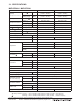
3-7. CAPACITY CORRECTION TABLE BY TEMPERATURE (5) M-Series Heating Correction Outdoor W.B. [° F] -13 -4 5 14 23 32 41 50 Indoor EAT DB MUZ-GE24NA 60 0.81 0.95 0.99 1.03 1.07 1.07 MUZ-GE18NA-1 60 0.67 0.82 0.94 1.04 1.07 1.07 MUZ-GE15NA-1 60 0.77 0.93 0.99 1.01 1.07 1.07 MUZ-GE12NA 60 0.68 0.83 0.94 1.04 1.07 1.07 MUZ-GE09NA 60 0.69 0.85 0.98 1.07 1.07 1.07 Interpolated Data Between 60 and 65 Indoor EAT DB data sets MUZ-GE24NA 63 0.80 0.93 0.97 1.01 1.
3-8. CAPACITY CORRECTION CURVE BY REFRIGERANT PIPING LENGTH DUE TO CONTINUING RESEARCH AND PRODUCT IMPROVEMENT, SPECIFICATIONS AND DATA ARE STILL UNDER REVIEW Due to continuing improvement, above specification may be subject to change without notice. M-Series - MSZ/MUZ-GE-NA Heat Pump Systems (August 2014) © 2014 Mitsubishi Electric US, Inc.
3-9. CAPACITY CORRECTION TABLE BY REFRIGERANT PIPING LENGTH (1) Cooling Capacity Correction Refrigerant piping length (one way: ft.) 25 (std.) 40 65 100 MUZ-GE09NA MUZ-GE12NA MUZ-GE15NA-1 MUZ-GE18NA-1 1.0 0.954 0.878 - MUZ-GE24NA 1.0 0.954 0.878 0.771 (2) Maximum Refrigerant Piping Length & Maximum Height Difference Refrigerant piping: ft Piping size: in.
3-9. CAPACITY CORRECTION TABLE BY REFRIGERANT PIPING LENGTH (3) M-Series Piping Correction Cooling Refrigerant piping length (ft) 25(std) 40 65 100 1.000 0.954 0.878 0.771 (4) M-Series Piping Correction Heating Refrigerant piping length (ft) 25(std) 40 65 100 1.000 0.989 0.972 0.955 Due to continuing improvement, above specification may be subject to change without notice. M-Series - MSZ/MUZ-GE-NA Heat Pump Systems (August 2014) © 2014 Mitsubishi Electric US, Inc.
3-10. CHARGE CALCULATIONS (1) Additional Refrigerant Charge (R410a: Oz.) NOTE: Refrigerant piping exceeding 25 ft. requires additional refrigerant charge according to the calcualation. Refrigerant piping length (one way): ft. Model MUZ-GE09NA MUZ-GE12NA MUZ-GE15NA-1 Outdoor unit precharged 25ft 30ft 40ft 50ft 60ft 65ft 0 1.62 4.86 8.10 11.34 12.96 1 lb. 12 oz. 2 lb. 9 oz. NOTE: Calculation: X oz. = 1.62/5 oz.
3-11. AIR FLOW DATA Outlet Air Speed And Coverage Model name MSZ-GE06NA-8 Mode Function Airflow (CFM) Air speed (ft./s.) Coverage (ft.) HEAT Dry 406 20.6 29.5 Dry 321 16.3 23.5 Wet 286 14.5 21.0 Dry 406 20.6 29.5 Dry 321 16.3 23.5 Wet 286 14.5 21.0 Dry 406 20.6 29.5 Dry 321 16.3 23.5 Wet 286 14.5 21.0 Dry 463 23.4 33.5 Dry 420 21.3 30.5 Wet 385 19.5 28.0 Dry 512 25.9 36.9 Dry 420 21.3 30.5 Wet 385 19.5 28.0 Dry 738 18.0 36.
3-12.
NC-40 30 NC-30 20 10 MSZ-GE24NA MSZ-GE24NA APPROXIMATE THRESHOLD OF HEARING FOR CONTINUOUS NOISE 63 NOTCH SPL(dB(A)) COOLING(Rated) 53 HEATING(Rated) 53 LINE NC-70 60 NC-60 50 NC-50 40 NC-40 30 NC-30 APPROXIMATE THRESHOLD OF HEARING FOR CONTINUOUS NOISE 63 OCTAVE BAND SOUND PRESSURE LEVEL, dB (0 dB = 0.0002 µbar) OCTAVE BAND SOUND PRESSURE LEVEL, dB (0 dB = 0.
3-12. SOUND PRESSURE LEVELS (2) Outdoor Unit Noise Criterion Curves MUZ-GE09NA MUZ-GE12NA UNIT 1m MICROPHONE Test Ambient temperature Cooling Heating NOTCH SPL(dB(A)) COOL HEAT 49 51 conditions are ● LINE ● □ based on □ JIS Z8731 DB:35℃ WB:24℃ DB: 7℃ WB: 6℃ 90 80 NC-70 OCTAVE BAND SOUND PRESSURE LEVEL,dB re 0.
3-12. SOUND PRESSURE LEVELS MUZ-GE12NA Noise Criterion Curves MUZ-GE12NA UNIT 1m MICROPHONE Test Ambient temperature Cooling Heating NOTCH SPL(dB(A)) COOL HEAT 49 51 conditions are ● LINE ● □ based on □ JIS Z8731 DB:35℃ WB:24℃ DB: 7℃ WB: 6℃ 90 80 NC-70 OCTAVE BAND SOUND PRESSURE LEVEL,dB re 0.
3-12. SOUND PRESSURE LEVELS MUZ-GE15NA-1 Noise Criterion Curves MUZ-GE15NA UNIT 1m MICROPHONE Test Ambient temperature Cooling Heating NOTCH SPL(dB(A)) COOL HEAT 49 51 conditions are ● LINE ● □ based on □ JIS Z8731 DB:35℃ WB:24℃ DB: 7℃ WB: 6℃ 90 80 NC-70 OCTAVE BAND SOUND PRESSURE LEVEL,dB re 0.
OCTA 20 NC-20 NC-20 10 3-12.
3-13. STANDARD OPERATION RANGE OPERATING RANGE (A) POWER SUPPLY Rated voltage Guaranteed Voltage (V) 208/230 V 1 phase 60 Hz Outdoor unit Min.187 208 230 Max.
3-14. MAXIMUM HEATING CAPACITY IN LOW AMBIENT TEMPERATURE MUZ-GE09NA MUZ-GE12NA MUZ-GE15NA-1 DUE TO CONTINUING RESEARCH AND PRODUCT IMPROVEMENT, SPECIFICATIONS AND DATA ARE STILL UNDER REVIEW Due to continuing improvement, above specification may be subject to change without notice. M-Series - MSZ/MUZ-GE-NA Heat Pump Systems (August 2014) © 2014 Mitsubishi Electric US, Inc.
3-14. MAXIMUM HEATING CAPACITY IN LOW AMBIENT TEMPERATURE MUZ-GE18NA 120% % Heating Capacity 100% 80% 60% 40% 20% 0% -15 -5 5 15 25 35 45 Outdoor Temperature Degrees (oF) HEATING CAPACITY Outdoor Temperature Degrees (oF) % Heating Capacity -13.0 34% -4.0 48% 5.0 63% 14.0 77% 23.0 88% 32.0 97% 41.0 100% 50.0 100% 69.8 100% MUZ-GE24NA MUZ-GE24NA 50000 45000 Heating Max Capacity (Btu/h) 40000 35000 30000 25000 20000 15000 10000 5000 0 -15 -5 5 15 25 35 45 55 65 75 50.0 38899 3.
3-15. ACCESSORIES (1) Indoor Unit Part Number Descriptions Applicable model C13-103 Blue Diamond Sensor Extension Cable - 15 Ft.
3-15. ACCESSORIES (1) Indoor Unit Cont.
3-15. ACCESSORIES (1) Indoor Unit Cont.
3-15.