SPLIT-TYPE AIR CONDITIONERS OUTDOOR UNIT SERVICE MANUAL HFC No. OBH629 utilized R410A Models MUZ-SF25VE MUZ-SF25VEH MUZ-SF35VE MUZ-SF35VEH - - - E1 - E1 - MUZ-SF42VE MUZ-SF42VEH MUZ-SF50VE MUZ-SF50VEH - E1 E1 E1 - E1 E1 - E1 Indoor unit service manual MSZ-SF•VE Series (OBH600) MUZ-SF25VE MUZ-SF25VEH MUZ-SF35VE MUZ-SF35VEH MUZ-SF42VE MUZ-SF42VEH CONTENTS 1. TECHNICAL CHANGES ··································· 3 2. PART NAMES AND FUNCTIONS ····················· 4 3.
Use the specified refrigerant only Never use any refrigerant other than that specified. Doing so may cause a burst, an explosion, or fire when the unit is being used, serviced, or disposed of. Correct refrigerant is specified in the manuals and on the spec labels provided with our products. We will not be held responsible for mechanical failure, system malfunction, unit breakdown or accidents caused by failure to follow the instructions. Prepare the proper tools.
1 TECHNICAL CHANGES MUZ-SF25VE MUZ-SF35VE MUZ-SF42VE MUZ-SF50VE - E1 - E1 - E1 - E1 MUZ-SF25VEH MUZ-SF35VEH MUZ-SF42VEH MUZ-SF50VEH - E1 - E1 - E1 - E1 1.
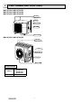
2 PART NAMES AND FUNCTIONS MUZ-SF25VE MUZ-SF25VEH MUZ-SF35VE MUZ-SF35VEH MUZ-SF42VE MUZ-SF42VEH Air inlet (back and side) Piping Drain hose Air outlet Drain outlet MUZ-SF50VE MUZ-SF50VEH Air inlet (back and side) Piping Drain hose Air outlet Drain outlet ACCESSORIES MODELS Drain socket OBH629 MUZ-SF25VE MUZ-SF35VE MUZ-SF42VE MUZ-SF50VE 1 4
3 SPECIFICATION MUZ-SF25VE MUZ-SF25VEH Outdoor model Power supply Capacity Rated frequency (Min.-Max.) Cooling Heating Electrical data Breaker Capacity Power input 1 (Total) Running current 1 (Total) Power factor 1 (Total) Model Output W A % A Cooling Heating W Cooling Current 1 A Heating Refrigeration oil (Model) L Model Fan motor Cooling Current 1 A Heating Dimensions W × H × D mm Weight kg Dehumidification Cooling /h High Cooling Low Air flow 1 High m3/h Heating Med.
Specifications and rated conditions of main electric parts Model MUZ-SF25VE MUZ-SF25VEH MUZ-SF35VE MUZ-SF35VEH MUZ-SF42VE MUZ-SF42VEH MUZ-SF50VE MUZ-SF50VEH Item (C61, C62) 620 μF 420 V Smoothing capacitor (C63) — 620 μF 420 V Diode module (DB61) 15 A 600 V 25 A 600 V (F61) T20AL250V Fuse (F701, F801, F901) T3.
MUZ-SF50VE MUZ-SF50VEH FUNCTION SPL(dB(A)) FUNCTION SPL(dB(A)) COOLING 50 COOLING 52 HEATING 51 HEATING 52 LINE 80 70 NC-70 60 NC-60 50 NC-50 40 NC-40 30 NC-30 20 NC-20 NC-10 10 LINE 90 90 63 125 250 500 1000 2000 4000 OCTAVE BAND SOUND PRESSURE LEVEL, dB re 0.0002 MICRO BAR OCTAVE BAND SOUND PRESSURE LEVEL, 0dB re 0.
5 OUTLINES AND DIMENSIONS Unit: mm MUZ-SF25VE MUZ-SF25VEH MUZ-SF35VE MUZ-SF35VEH MUZ-SF42VE MUZ-SF42VEH REQUIRED SPACE 100 mm or more Drain hole ø42 (MUZ-SF25/35/42VE) Drain hole ø33 (MUZ-SF25/35/42VEH) 100 re r mo mo m 100 mm or m ore Bolt pitch for installation 304~325 44 285 344.5 400 Air in Air in 350 mm or m ore 200 mm or more 17.5 40 2 holes 10 X 21 Air out 22.3 Service panel 23 69 302.5 Gas refrigerant pipe joint Refrigerant pipe (flared) ø9.52 99.5 10 164.
6 WIRING DIAGRAM MUZ-SF25VE MUZ-SF35VE MUZ-SF25VEH MUZ-SF35VEH OBH629 9
MUZ-SF42VE MUZ-SF50VE MUZ-SF42VEH MUZ-SF50VEH OBH629 10
7 REFRIGERANT SYSTEM DIAGRAM MUZ-SF25VE MUZ-SF25VEH MUZ-SF35VE MUZ-SF35VEH Refrigerant pipe ø9.52 (with heat insulator) Unit: mm 4-way valve Muffler Stop valve Discharge temperature thermistor RT62 Flared connection Outdoor heat exchanger Muffler Outdoor heat exchanger temperature thermistor RT68 Ambient temperature thermistor RT65 Compressor Defrost thermistor RT61 Strainer #100 Flared connection Refrigerant pipe ø6.35 (with heat insulator) Capillary tube ø3.0×ø2.0×240 LEV R.V.
MUZ-SF50VE MUZ-SF50VEH Unit: mm Muffler 4-way valve #100 Refrigerant pipe ø12.7 (with heat insulator) Stop valve (with service port) Flared connection Discharge temperature thermistor RT62 Outdoor heat exchanger Defrost thermistor RT61 Amb tem ther RT6 Compressor Outdoor heat exchanger temperature thermistor RT68 Capillary tube ø3.0×ø2.0×200(×4) Flared connection LEV Strainer #100 Stop valve Refrigerant pipe ø6.35 (with heat insulator) Strainer #100 Muffler Capillary tube ø4.0×ø2.
8 PERFORMANCE CURVES MUZ-SF25VE MUZ-SF25VEH MUZ-SF35VE MUZ-SF35VEH MUZ-SF42VE MUZ-SF42VEH MUZ-SF50VE MUZ-SF50VEH The standard specifications apply only to the operation of the air conditioner under normal conditions. Since operating conditions vary according to the areas where these units are installed, the following information has been provided to clarify the operating characteristics of the air conditioner under the conditions indicated by the performance curve.
8.6 10.7 12.0 5.3 7.8 9.7 10.8 4.8 7.0 8.6 9.6 4.3 6.2 7.6 8.5 3.8 5.4 6.7 7.4 Input correction factors 5.9 1.3 1.2 22 20 18 24 26 1.1 1.0 0.9 Indoor intake air Wet-bulb temperature( ) 0.8 -10 MUZ-SF50VE MUZ-SF50VEH 13.3 MUZ-SF42VE MUZ-SF42VEH 11.8 MUZ-SF35VE MUZ-SF35VEH 9.5 MUZ-SF25VE MUZ-SF25VEH Indoor air Wet-bulb temperature difference (°C) Total input (Cooling : at Rated frequency) 6.
8-2. CAPACITY AND INPUT CORRECTION BY OPERATIONAL FREQUENCY OF COMPRESSOR 0.5 0.0 0 50 100 The operational frequency of compressor (Hz) 1.5 1.0 0.5 0.0 0 1.5 Correction of Heating capacity Input correction factors 1.0 Correction of Cooling input 2.0 Capacity correction factors 1.5 Input correction factors Capacity correction factors MUZ-SF25VE MUZ-SF25VEH Correction of Cooling capacity 1.0 0.5 0.0 0 50 100 The operational frequency of compressor (Hz) Correction of Heating input 2.0 1.
8-3. HOW TO OPERATE FIXED-FREQUENCY OPERATION 1. Press EMERGENCY OPERATION switch to start COOL or HEAT mode (COOL: Press once, HEAT: Press twice). 2. Test run operation starts and continues to operate for 30 minutes. 3. Compressor operates at rated frequency in COOL mode or 58 Hz in HEAT mode. 4. Indoor fan operates at High speed. 5. After 30 minutes, test run operation finishes and EMERGENCY OPERATION starts (operation frequency of compressor varies). 6.
2.5 2.0 1.5 15 MUZ-SF35VE MUZ-SF35VEH 5.0 Outdoor current (A) Outdoor current (A) 3.0 20 25 30 4.5 4.0 3.5 3.0 15 35 Ambient temperature (°C) Ambient humidity(%) MUZ-SF42VE MUZ-SF42VEH 6.0 Outdoor current (A) Outdoor unit current MUZ-SF25VE MUZ-SF25VEH 20 25 30 35 5.5 5.0 4.5 4.0 3.
PERFORMANCE DATA COOL operation at Rated frequency MUZ-SF25VE MUZ-SF25VEH CAPACITY: 2.5 kW INDOOR INDOOR DB (°C) WB (°C) SHF: 0.92 INPUT: 600 W OUTDOOR DB (°C) 21 25 27 30 SHF INPUT 21 18 2.94 2.17 0.74 480 2.81 2.08 0.74 504 2.70 2.00 0.74 528 2.60 1.92 0.74 552 21 20 3.06 1.90 0.62 504 2.94 1.82 0.62 534 2.85 1.77 0.62 546 2.75 1.71 0.62 570 22 18 2.94 2.29 0.78 480 2.81 2.19 0.78 504 2.70 2.11 0.78 528 2.60 2.03 0.78 552 22 20 3.06 2.
PERFORMANCE DATA COOL operation at Rated frequency MUZ-SF25VE MUZ-SF25VEH CAPACITY: 2.5 kW INDOOR INDOOR DB (°C) WB (°C) SHF: 0.92 INPUT: 600 W OUTDOOR DB (°C) 35 40 46 SHF INPUT 21 18 2.45 1.81 0.74 588 2.25 1.67 0.74 624 2.08 1.54 0.74 648 21 20 2.58 1.60 0.62 612 2.40 1.49 0.62 642 2.23 1.38 0.62 678 22 18 2.45 1.91 0.78 588 2.25 1.76 0.78 624 2.08 1.62 0.78 648 22 20 2.58 1.70 0.66 612 2.40 1.58 0.66 642 2.23 1.47 0.66 678 22 22 2.73 1.
PERFORMANCE DATA COOL operation at Rated frequency MUZ-SF35VE MUZ-SF35VEH CAPACITY: 3.5 kW INDOOR INDOOR DB (°C) WB (°C) SHF: 0.80 INPUT: 1080 W OUTDOOR DB (°C) 21 25 27 30 Q SHC SHF INPUT Q SHC SHF INPUT Q SHC SHF INPUT Q SHC SHF INPUT 21 18 4.11 2.55 0.62 864 3.94 2.44 0.62 907 3.78 2.34 0.62 950 3.64 2.26 0.62 994 21 20 4.29 2.14 0.50 907 4.11 2.06 0.50 961 3.99 2.00 0.50 983 3.85 1.93 0.50 1026 22 18 4.11 2.71 0.66 864 3.94 2.60 0.
PERFORMANCE DATA COOL operation at Rated frequency MUZ-SF35VE MUZ-SF35VEH CAPACITY: 3.5 kW INDOOR INDOOR DB (°C) WB (°C) SHF: 0.80 INPUT: 1080 W OUTDOOR DB (°C) 35 40 46 Q SHC SHF INPUT Q SHC SHF INPUT Q SHC SHF INPUT 21 18 3.43 2.13 0.62 1058 3.15 1.95 0.62 1123 2.91 1.80 0.62 1166 21 20 3.61 1.80 0.50 1102 3.36 1.68 0.50 1156 3.12 1.56 0.50 1220 22 18 3.43 2.26 0.66 1058 3.15 2.08 0.66 1123 2.91 1.92 0.66 1166 22 20 3.61 1.95 0.54 1102 3.
PERFORMANCE DATA COOL operation at Rated frequency MUZ-SF42VE MUZ-SF42VEH CAPACITY: 4.2 kW INDOOR INDOOR DB (°C) WB (°C) SHF: 0.72 INPUT: 1340 W OUTDOOR DB (°C) 21 25 27 30 Q SHC SHF INPUT Q SHC SHF INPUT Q SHC SHF INPUT Q SHC SHF INPUT 21 18 4.94 2.66 0.54 1072 4.73 2.55 0.54 1126 4.54 2.45 0.54 1179 4.37 2.36 0.54 1233 21 20 5.15 2.16 0.42 1126 4.94 2.07 0.42 1193 4.79 2.01 0.42 1219 4.62 1.94 0.42 1273 22 18 4.94 2.86 0.58 1072 4.73 2.
PERFORMANCE DATA COOL operation at Rated frequency MUZ-SF42VE MUZ-SF42VEH CAPACITY: 4.2 kW INDOOR INDOOR DB (°C) WB (°C) SHF: 0.72 INPUT: 1340 W OUTDOOR DB (°C) 35 40 46 SHF INPUT 21 18 4.12 2.22 0.54 1313 3.78 2.04 0.54 1394 3.49 1.88 0.54 1447 21 20 4.33 1.82 0.42 1367 4.03 1.69 0.42 1434 3.74 1.57 0.42 1514 22 18 4.12 2.39 0.58 1313 3.78 2.19 0.58 1394 3.49 2.02 0.58 1447 22 20 4.33 1.99 0.46 1367 4.03 1.85 0.46 1434 3.74 1.72 0.
PERFORMANCE DATA COOL operation at Rated frequency MUZ-SF50VE MUZ-SF50VEH CAPACITY: 5.0 kW INDOOR INDOOR DB (°C) WB (°C) SHF: 0.70 INPUT: 1660 W OUTDOOR DB (°C) 21 25 27 30 SHF INPUT 21 18 5.88 3.06 0.52 1328 5.63 2.93 0.52 1394 5.40 2.81 0.52 1461 5.20 2.70 0.52 1527 21 20 6.13 2.45 0.40 1394 5.88 2.35 0.40 1477 5.70 2.28 0.40 1511 5.50 2.20 0.40 1577 22 18 5.88 3.29 0.56 1328 5.63 3.15 0.56 1394 5.40 3.02 0.56 1461 5.20 2.91 0.
PERFORMANCE DATA COOL operation at Rated frequency MUZ-SF50VE MUZ-SF50VEH CAPACITY: 5.0 kW INDOOR INDOOR DB (°C) WB (°C) SHF: 0.70 INPUT: 1660 W OUTDOOR DB (°C) 35 40 46 SHF INPUT 21 18 4.90 2.55 0.52 1627 4.50 2.34 0.52 1726 4.15 2.16 0.52 1793 21 20 5.15 2.06 0.40 1693 4.80 1.92 0.40 1776 4.45 1.78 0.40 1876 22 18 4.90 2.74 0.56 1627 4.50 2.52 0.56 1726 4.15 2.32 0.56 1793 22 20 5.15 2.27 0.44 1693 4.80 2.11 0.44 1776 4.45 1.96 0.
PERFORMANCE DATA HEAT operation at Rated frequency MUZ-SF25VE MUZ-SF25VEH CAPACITY: 3.2 kW INDOOR DB (°C) INPUT: 780 W OUTDOOR WB (°C) -10 -5 0 5 10 15 20 Q INPUT Q INPUT Q INPUT Q INPUT Q INPUT Q INPUT Q INPUT 15 2.02 507 2.43 608 2.85 686 3.26 741 3.68 788 4.06 811 4.48 827 21 1.92 546 2.30 647 2.72 718 3.10 772 3.52 811 3.90 835 4.30 866 26 1.73 585 2.14 686 2.53 757 2.94 811 3.36 850 3.74 874 4.
9 ACTUATOR CONTROL MUZ-SF25VE MUZ-SF25VEH MUZ-SF35VE MUZ-SF35VEH MUZ-SF42VE MUZ-SF42VEH MUZ-SF50VE MUZ-SF50VEH 9-1. OUTDOOR FAN MOTOR CONTROL The fan motor turns ON/OFF, interlocking with the compressor. [ON] The fan motor turns ON 5 seconds before the compressor starts up. [OFF] The fan motor turns OFF 15 seconds after the compressor has stopped running. 5 seconds 15 seconds ON Compressor OFF ON Outdoor fan motor OFF 9-2. R.V. COIL CONTROL Heating . . . . . . . . . . . . . . . . . ON Cooling . . . .
10 SERVICE FUNCTIONS MUZ-SF25VE MUZ-SF25VEH MUZ-SF35VE MUZ-SF35VEH MUZ-SF42VE MUZ-SF42VEH MUZ-SF50VE MUZ-SF50VEH 10-1. CHANGE IN DEFROST SETTING Changing defrost finish temperature To change the defrost finish temperature, cut/solder the JS wire of the outdoor inverter P.C. board. (Refer to 11-6-1.) Defrost finish temperature (°C) MUZ-SF25/35/42 MUZ-SF50 5 9 10 18 Jumper wire JS Soldered (Initial setting) None (Cut) 10-2.
11-2. FAILURE MODE RECALL FUNCTION Outline of the function This air conditioner can memorize the abnormal condition which has occurred once. Even though LED indication listed on the troubleshooting check table (11-3.) disappears, the memorized failure details can be recalled. 1. Flow chart of failure mode recall function for the indoor/outdoor unit Operational procedure The cause of abnormality cannot be found because the abnormality does not recur.
2. Flow chart of the detailed outdoor unit failure mode recall function Operational procedure The outdoor unit might be abnormal. Confirm if outdoor unit is abnormal according to the following procedures. Confirm that the remote controller is in the failure mode recall function. With the remote controller headed towards the indoor unit, press TEMP button to adjust the set temperature to 25°C. 1 Does the left lamp of OPERATION INDICATOR lamp on the indoor unit blink at the interval of 0.
3. Outdoor unit failure mode table The left lamp of OPERATION Abnormal point INDICATOR (Failure mode/protection) lamp (Indoor unit) OFF None (Normal) 1-time flash 2.5 seconds OFF LED indication (Outdoor P.C. board) Condition Remedy — — — ○ ○ ○ ○ ○ ○ • Reconnect compressor connector. • Refer to 11-5. "How to check inverter/ compressor". • Check stop valve. — ○ • Reconnect compressor connector. • Refer to 11-5. "How to check inverter/ compressor".
11-3. TROUBLESHOOTING CHECK TABLE No. 1 Symptom Outdoor unit does not operate. Abnormal point/ Condition 1-time flash every Outdoor power sys2.5 seconds tem LED indication 2 3 6 6-time flash 2.5 seconds OFF 11-time flash 2.5 seconds OFF 14-time flash 2.5 seconds OFF 7 16-time flash 2.5 seconds OFF 4 5 8 9 4-way valve/ Pipe temperature Overcurrent protection 4-time flash 2.5 seconds OFF Fin temperature /P.C.
11-4. TROUBLE CRITERION OF MAIN PARTS MUZ-SF25VE MUZ-SF25VEH MUZ-SF35VE MUZ-SF35VEH MUZ-SF42VE MUZ-SF42VEH MUZ-SF50VE MUZ-SF50VEH Part name Defrost thermistor (RT61) Fin temperature thermistor (RT64) Ambient temperature thermistor (RT65) Check method and criterion Figure Measure the resistance with a tester. Refer to 11-6. “Test point diagram and voltage”, 1. “Inverter P.C. board”, for the chart of thermistor.
11-5. TROUBLESHOOTING FLOW A How to check inverter/compressor Disconnect the connector between compressor and the intelligent power module (IC700). See 11-5. Check the voltage between terminals. Are the voltages balanced? Yes No Replace the inverter P.C. board. See 11-5. Check the compressor. “Check of open phase”. “Check of compressor”.
D Check of compressor winding ●Disconnect the connector between the compressor and intelligent power module, and measure the resistance between the compressor terminals. <> at 3 points BLK-WHT Measure the resistance between the lead wires at 3 points. BLK-RED WHT-RED <> Refer to 11-4. 0 [Ω] ················Abnormal [short] Infinite [Ω] ·······Abnormal [open] NOTE: Be sure to zero the ohmmeter before measurement.
G Check of outdoor thermistors Disconnect the connector of thermistor in the outdoor P.C. board (see below table), and measure the resistance of thermistor. Is the resistance of thermistor normal? (Refer to 11-6.1.) Yes No Replace the thermistor except RT64. When RT64 is abnormal, replace the inverter P.C. board. Reconnect the connector of thermistor. Turn ON the power supply and press EMERGENCY OPERATION switch.
I Check of outdoor fan motor Disconnect the connectors CN931 and CN932 from the inverter P.C. board. Check the connection between the connector CN931 and CN932. Is the resistance between each terminal of outdoor fan motor normal? (Refer to 11-4.) No Yes Disconnect CN932 from the inverter P.C. board, and turn on the power supply. Rotate the outdoor fan motor manually and measure the voltage of CN931.
J Check of power supply Disconnect the connector between compressor and intelligent power module. Turn ON power supply and press EMERGENCY OPERATION switch. Does The left lamp of OPERATION INDICATOR lamp on the indoor unit light up? Yes Is there voltage 260 - 370 VDC between DB61 (+) and DB61 (–) on the inverter P.C. board? (Refer to 11-6.1.) No Check the electric parts in main circuit. Rectify indoor/outdoor connecting wire.
K Check of LEV (Expansion valve) Turn ON the power supply. While pressing both OPERATION SELECT button and TEMP button on the remote controller at the same time, press RESET button. First, release RESET button. Hold down the other two buttons for another 3 seconds. Confirm that the indicators on the LCD screen shown in the right figure are all displayed. Then release the buttons.
L Check of inverter P.C. board Check the outdoor fan motor. (Refer to 11-5. .) Is the fuse (F901) blown on the inverter P.C. board? Yes No Check the connection of the connectors (CN931, CN932) of the outdoor fan motor. If the connection is poor, make it correct. Operate the outdoor unit by starting EMERGENCY OPERATION. Check the LED indication on the inverter P.C. board. Does the LED flash 10 times? Yes (10-time flash) No Check the corresponding parts following LED indication. (Refer to 11-3.
M How to check miswiring and serial signal error Turn the main power supply OFF. Is there rated voltage in the power supply? Yes Check the power supply. No Check for incorrect indoor-outdoor connecting wiring. Was the indoor unit ever connected to the Multi (MXZ) series and operated (turned on)? Yes No The connection information to the Multi series is stored in the indoor unit. Refer to “Deleting the memorized abnormal condition” described in 11-2.1 to clear the error history.
N Electromagnetic noise enters into TV sets or radios Is the unit earthed? Yes Is the distance between the antennas and the indoor unit within 3 m, or is the distance between the antennas and the outdoor unit within 3 m? No Earth the unit. No Yes Extend the distance between the antennas and the indoor unit, and/or the antennas and the outdoor unit.
O Check of defrost heater MUZ-SF•VEH Check the following points before checking electric continuity. 1. Does the resistance of ambient temperature thermistor have the characteristics? Refer to 11-6.1. 2. Is the resistance of defrost heater normal? Refer to 11-4. 3. Does the heater protector remain conducted (not open)? 4.
11-6. TEST POINT DIAGRAM AND VOLTAGE 1. Inverter P.C. board MUZ-SF25VE MUZ-SF25VEH MUZ-SF35VE MUZ-SF35VEH MUZ-SF42VE MUZ-SF42VEH MUZ-SF50VE MUZ-SF50VEH DB61 260 - 370 VDC (-) (+) Back side of unit Smoothing capacitor (C62) Smoothing capacitor (C63) MUZ-SF42/50 Smoothing capacitor (C61) Fuse (F801) T3.15AL250V 230 VAC Heater connector (CN722) R.V.coil MUZ-SF25/35VEH (CN721) MUZ-SF42/50VEH 230 VAC Fuse (F701) T3.15AL250V Fuse (F901) T3.
12 DISASSEMBLY INSTRUCTIONS <"Terminal with locking mechanism" Detaching points> The terminal which has the locking mechanism can be detached as shown below. There are two types (refer to (1) and (2)) of the terminal with locking mechanism. The terminal without locking mechanism can be detached by pulling it out. Check the shape of the terminal before detaching. (1) Slide the sleeve and check if there is a locking lever or not.
OPERATING PROCEDURE PHOTOS 2. Removing the inverter assembly, inverter P.C. board (1) Remove the cabinet and panels. (Refer to 1.) (2) Disconnect the lead wire to the reactor and the following connectors: CN721 (R.V.
OPERATING PROCEDURE PHOTOS 5. Removing outdoor fan motor Photo 6 (1) Remove the cabinet and panels. (Refer to 1.) (2) Disconnect the following connectors: CN931, CN932 (Fan motor) (3) Remove the propeller nut. (4) Remove the propeller. (5) Remove the screws fixing the fan motor. (6) Remove the fan motor. Ambient temperature thermistor Outdoor heat exchanger temperature thermistor 6. Removing the compressor and 4-way valve (1) Remove the cabinet and panels. (Refer to 1.
12-2. MUZ-SF50VE MUZ-SF50VEH NOTE: Turn OFF power supply before disassembly. OPERATING PROCEDURE PHOTOS 1. Removing the cabinet Photo 1 (1) (2) (3) (4) (5) (6) (7) Remove the screws of the service panel. Remove the screws of the top panel. Remove the screw of the valve cover. Remove the service panel. Remove the top panel. Remove the valve cover. Disconnect the power supply and indoor/outdoor connecting wire. (8) Remove the screws of the cabinet. (9) Remove the cabinet.
OPERATING PROCEDURE PHOTOS 2. Removing the inverter assembly, inverter P.C. board Photo 3 Screw of the terminal (1) Remove the cabinet and panels. (Refer to 1.) Screw of the heat sink block support and the (2) Disconnect the lead wire to the reactor and the following con- support and the separator back panel nectors: CN721 (R.V.
OPERATING PROCEDURE PHOTOS 4. Removing the discharge temperature thermistor, defrost thermistor, outdoor heat exchanger temperature thermistor and ambient temperature thermistor Photo 6 Outdoor heat exchanger temperature thermistor (1) Remove the cabinet and panels. (Refer to 1.) (2) Disconnect the lead wire to the reactor and the following connectors:
OBH629 51
HEAD OFFICE: TOKYO BLDG., 2-7-3, MARUNOUCHI, CHIYODA-KU, TOKYO 100-8310, JAPAN © Copyright 2012 MITSUBISHI ELECTRIC CORPORATION Distributed in Nov. 2012. No. OBH629 Made in Japan New publication, effective Nov. 2012 Specifications are subject to change without notice.