
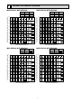
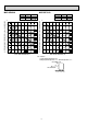
Service manual


9
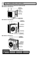
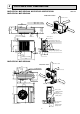
Unit: mm
MUZ-GE25VA MUZ-GE25VAH MUZ-GE35VA MUZ-GE35VAH
MUZ-GE42VA MUZ-GE42VAH
10
69
800
302.5
500 Bolt pitch for installation
150
22.3
Handle
550
280
164.5
99.5
170.5
23
Service panel
Service port
285
344.5
44
400
Air in
Air out
Air in
17.5
Bolt pitch for
installation
304~325
40
Liquid refrigerant pipe joint
Refrigerant pipe (flared) ø6.35
Gas refrigerant pipe joint
Refrigerant pipe (flared) ø9.52
43
35
2 holes 10 X 21
REQUIRED SPACE
100 mm or more
350 mm or more
200 mm or more
100 mm or more
100 mm or more
Drain hole ø42 (MUZ-GE25/35/42VA)
Drain hole ø33 (MUZ-GE25/35/42VAH)
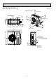
MUZ-GE50VA MUZ-GE50VAH
OUTLINES AND DIMENSIONS
5
30°
35°
155
90
198
40
515
299
66
34
51
330
360
850
430
500
80
121
840
Service panel
Gas refrigerant
pipe joint
Refrigerant pipe
(flared) ø12.7
Liquid refrigerant
pipe joint
Refrigerant pipe
(flared) ø6.35
170
500 mm or more
100 mm or more
500 mm or more
350 mm or more
100 mm or more
REQUIRED SPACE
Air in
Air out
Air in
4 holes 10 × 21
Drain holes ø33(MUZ-GE50VA)