
Service manual

58
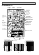
-20 -10 0 10 20 30 40
0
10
20
30
40
50
60
70
80
90
100
Temperature( )
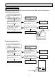
Defrost thermistor(RT61)
Ambient temperature thermistor(RT65)
Outdoor heat exchanger temperature thermistor(RT68)
Temperature( )
Discharge temperature thermistor(RT62)
0 102030405060708090100110120
0
100
200
300
400
500
600
700
0 1020304050607080
0
20
40
60
80
100
120
140
160
180
200
Temperature( )
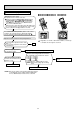
Fin temperature thermistor(RT64)
Resistance(k )
Resistance(k )
Resistance(k )
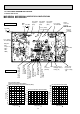
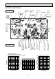
1. Inverter P.C. board
MUZ-GE25VA MUZ-GE25VAH MUZ-GE35VA MUZ-GE35VAH
MUZ-GE42VA MUZ-GE42VAH
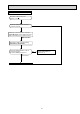
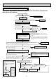
11-6. TEST POINT DIAGRAM AND VOLTAGE
Fin temperature
thermistor/RT64
(CN642)
Ambient temperature
thermistor/RT65
(CN643)
Discharge temperature
thermistor/RT62
(CN641)
Defrost thermistor
/RT61(CN641)
LEV
connector
(CN724)
DB61
280 - 370 VDC
Front side of unit
230 VAC
Smoothing
capacitor
(C62)
Output to
drive
compressor
(LDU,
LDV,
LDW)
(+)
(-)
Fuse (F701)
T3.15AL250V
Smoothing
capacitor
(C61)
Smoothing
capacitor
(C63)
Fuse (F901)
T3.15AL250V
R.V.coil
(CN721)
230 VAC
Jumper wire for
changing defrost
setting (JS)
Output to drive outdoor
fan motor (CN932)
230 VAC
Outdoor heat exchanger
temperature thermistor
/RT68 (CN644)
Jumper wire
for pre-heat
control setting
(JK)
Heater
connector
(CN722)
MUZ-GE•VAH
Fuse (F801)
T3.15AL250V
Back side of unit
LED